stm32内部高速晶振打开作为主时钟
首先建议你别这么干,因为内部晶振特别容易受温度等外界影响,很容易卡死或堵死程序
我是因为没画外部晶振电路,所以只能开内部晶振来作为时钟
适用于stm32f103系列
把下面的代码换掉源文件里的时钟源配置
/* 开启HSI 即内部晶振时钟 */RCC->CR |= (uint32_t)0x00000001;
//  RCC_DeInit();
//  RCC_HSEConfig(RCC_HSE_ON);  //使能内部时钟 HSI/*选择HSI为PLL的时钟源HSI必须2分频给PLL*/RCC->CFGR |= (uint32_t)RCC_CFGR_PLLSRC_HSI_Div2; /*PLLCLK=8/2*9=36MHz   设置倍频得到时钟源PLL的频率*/RCC->CFGR |= (uint32_t)RCC_CFGR_PLLMULL9;/* PLL不分频输出  */RCC->CFGR |= (uint32_t)RCC_CFGR_HPRE_DIV1;/* 使能 PLL时钟 */RCC->CR |= RCC_CR_PLLON;/* 等待PLL时钟就绪*/while((RCC->CR & RCC_CR_PLLRDY) == 0){}/* 选择PLL为系统时钟的时钟源 */RCC->CFGR &= (uint32_t)((uint32_t)~(RCC_CFGR_SW));RCC->CFGR |= (uint32_t)RCC_CFGR_SW_PLL;    /* 等到PLL成为系统时钟的时钟源*/while ((RCC->CFGR & (uint32_t)RCC_CFGR_SWS) != (uint32_t)0x08){}
我的时钟配置文件
system_stm32f10x.c
/********************************************************************************* @file system_stm32f10x.c* @author MCD Application Team* @version V3.5.0* @date 11-March-2011* @brief CMSIS Cortex-M3 Device Peripheral Access Layer System Source File.* * 1. This file provides two functions and one global variable to be called from * user application:* - SystemInit(): Setups the system clock (System clock source, PLL Multiplier* factors, AHB/APBx prescalers and Flash settings). * This function is called at startup just after reset and * before branch to main program. This call is made inside* the "startup_stm32f10x_xx.s" file.** - SystemCoreClock variable: Contains the core clock (HCLK), it can be used* by the user application to setup the SysTick * timer or configure other parameters.* * - SystemCoreClockUpdate(): Updates the variable SystemCoreClock and must* be called whenever the core clock is changed* during program execution.** 2. After each device reset the HSI (8 MHz) is used as system clock source.* Then SystemInit() function is called, in "startup_stm32f10x_xx.s" file, to* configure the system clock before to branch to main program.** 3. If the system clock source selected by user fails to startup, the SystemInit()* function will do nothing and HSI still used as system clock source. User can * add some code to deal with this issue inside the SetSysClock() function.** 4. The default value of HSE crystal is set to 8 MHz (or 25 MHz, depedning on* the product used), refer to "HSE_VALUE" define in "stm32f10x.h" file. * When HSE is used as system clock source, directly or through PLL, and you* are using different crystal you have to adapt the HSE value to your own* configuration.* ******************************************************************************* @attention** THE PRESENT FIRMWARE WHICH IS FOR GUIDANCE ONLY AIMS AT PROVIDING CUSTOMERS* WITH CODING INFORMATION REGARDING THEIR PRODUCTS IN ORDER FOR THEM TO SAVE* TIME. AS A RESULT, STMICROELECTRONICS SHALL NOT BE HELD LIABLE FOR ANY* DIRECT, INDIRECT OR CONSEQUENTIAL DAMAGES WITH RESPECT TO ANY CLAIMS ARISING* FROM THE CONTENT OF SUCH FIRMWARE AND/OR THE USE MADE BY CUSTOMERS OF THE* CODING INFORMATION CONTAINED HEREIN IN CONNECTION WITH THEIR PRODUCTS.** <h2><center>© COPYRIGHT 2011 STMicroelectronics</center></h2>*******************************************************************************//** @addtogroup CMSIS* @{*//** @addtogroup stm32f10x_system* @{*/ /** @addtogroup STM32F10x_System_Private_Includes* @{*/#include "stm32f10x.h"/*** @}*//** @addtogroup STM32F10x_System_Private_TypesDefinitions* @{*//*** @}*//** @addtogroup STM32F10x_System_Private_Defines* @{*//*!< Uncomment the line corresponding to the desired System clock (SYSCLK)frequency (after reset the HSI is used as SYSCLK source)IMPORTANT NOTE:============== 1. After each device reset the HSI is used as System clock source.2. Please make sure that the selected System clock doesn't exceed your device'smaximum frequency.3. If none of the define below is enabled, the HSI is used as System clocksource.4. The System clock configuration functions provided within this file assume that:- For Low, Medium and High density Value line devices an external 8MHz crystal is used to drive the System clock.- For Low, Medium and High density devices an external 8MHz crystal isused to drive the System clock.- For Connectivity line devices an external 25MHz crystal is used to drivethe System clock.If you are using different crystal you have to adapt those functions accordingly.*/#if defined (STM32F10X_LD_VL) || (defined STM32F10X_MD_VL) || (defined STM32F10X_HD_VL)
/* #define SYSCLK_FREQ_HSE HSE_VALUE */#define SYSCLK_FREQ_24MHz 24000000
#else
/* #define SYSCLK_FREQ_HSE HSE_VALUE */
/* #define SYSCLK_FREQ_24MHz 24000000 */
/* #define SYSCLK_FREQ_36MHz 36000000 */
/* #define SYSCLK_FREQ_48MHz 48000000 */
/* #define SYSCLK_FREQ_56MHz 56000000 */
#define SYSCLK_FREQ_72MHz 72000000
#endif/*!< Uncomment the following line if you need to use external SRAM mountedon STM3210E-EVAL board (STM32 High density and XL-density devices) or on STM32100E-EVAL board (STM32 High-density value line devices) as data memory */
#if defined (STM32F10X_HD) || (defined STM32F10X_XL) || (defined STM32F10X_HD_VL)
/* #define DATA_IN_ExtSRAM */
#endif/*!< Uncomment the following line if you need to relocate your vector Table inInternal SRAM. */
/* #define VECT_TAB_SRAM */
#define VECT_TAB_OFFSET 0x0 /*!< Vector Table base offset field. This value must be a multiple of 0x200. *//*** @}*//** @addtogroup STM32F10x_System_Private_Macros* @{*//*** @}*//** @addtogroup STM32F10x_System_Private_Variables* @{*//*******************************************************************************
* Clock Definitions
*******************************************************************************/
#ifdef SYSCLK_FREQ_HSEuint32_t SystemCoreClock = SYSCLK_FREQ_HSE; /*!< System Clock Frequency (Core Clock) */
#elif defined SYSCLK_FREQ_24MHzuint32_t SystemCoreClock = SYSCLK_FREQ_24MHz; /*!< System Clock Frequency (Core Clock) */
#elif defined SYSCLK_FREQ_36MHzuint32_t SystemCoreClock = SYSCLK_FREQ_36MHz; /*!< System Clock Frequency (Core Clock) */
#elif defined SYSCLK_FREQ_48MHzuint32_t SystemCoreClock = SYSCLK_FREQ_48MHz; /*!< System Clock Frequency (Core Clock) */
#elif defined SYSCLK_FREQ_56MHzuint32_t SystemCoreClock = SYSCLK_FREQ_56MHz; /*!< System Clock Frequency (Core Clock) */
#elif defined SYSCLK_FREQ_72MHzuint32_t SystemCoreClock = SYSCLK_FREQ_72MHz; /*!< System Clock Frequency (Core Clock) */
#else /*!< HSI Selected as System Clock source */uint32_t SystemCoreClock = HSI_VALUE; /*!< System Clock Frequency (Core Clock) */
#endif__I uint8_t AHBPrescTable[16] = {0, 0, 0, 0, 0, 0, 0, 0, 1, 2, 3, 4, 6, 7, 8, 9};
/*** @}*//** @addtogroup STM32F10x_System_Private_FunctionPrototypes* @{*/static void SetSysClock(void);#ifdef SYSCLK_FREQ_HSEstatic void SetSysClockToHSE(void);
#elif defined SYSCLK_FREQ_24MHzstatic void SetSysClockTo24(void);
#elif defined SYSCLK_FREQ_36MHzstatic void SetSysClockTo36(void);
#elif defined SYSCLK_FREQ_48MHzstatic void SetSysClockTo48(void);
#elif defined SYSCLK_FREQ_56MHzstatic void SetSysClockTo56(void);
#elif defined SYSCLK_FREQ_72MHzstatic void SetSysClockTo72(void);
#endif#ifdef DATA_IN_ExtSRAMstatic void SystemInit_ExtMemCtl(void);
#endif /* DATA_IN_ExtSRAM *//*** @}*//** @addtogroup STM32F10x_System_Private_Functions* @{*//*** @brief Setup the microcontroller system* Initialize the Embedded Flash Interface, the PLL and update the * SystemCoreClock variable.* @note This function should be used only after reset.* @param None* @retval None*/
void SystemInit (void)
{
#ifdef USE_HSE_CLOCK /* Reset the RCC clock configuration to the default reset state(for debug purpose) *//* Set HSION bit */RCC->CR |= (uint32_t)0x00000001;/* Reset SW, HPRE, PPRE1, PPRE2, ADCPRE and MCO bits */
#ifndef STM32F10X_CLRCC->CFGR &= (uint32_t)0xF8FF0000;
#elseRCC->CFGR &= (uint32_t)0xF0FF0000;
#endif /* STM32F10X_CL */ /* Reset HSEON, CSSON and PLLON bits */RCC->CR &= (uint32_t)0xFEF6FFFF;/* Reset HSEBYP bit */RCC->CR &= (uint32_t)0xFFFBFFFF;/* Reset PLLSRC, PLLXTPRE, PLLMUL and USBPRE/OTGFSPRE bits */RCC->CFGR &= (uint32_t)0xFF80FFFF;#ifdef STM32F10X_CL/* Reset PLL2ON and PLL3ON bits */RCC->CR &= (uint32_t)0xEBFFFFFF;/* Disable all interrupts and clear pending bits */RCC->CIR = 0x00FF0000;/* Reset CFGR2 register */RCC->CFGR2 = 0x00000000;
#elif defined (STM32F10X_LD_VL) || defined (STM32F10X_MD_VL) || (defined STM32F10X_HD_VL)/* Disable all interrupts and clear pending bits */RCC->CIR = 0x009F0000;/* Reset CFGR2 register */RCC->CFGR2 = 0x00000000;
#else/* Disable all interrupts and clear pending bits */RCC->CIR = 0x009F0000;
#endif /* STM32F10X_CL */#if defined (STM32F10X_HD) || (defined STM32F10X_XL) || (defined STM32F10X_HD_VL)#ifdef DATA_IN_ExtSRAMSystemInit_ExtMemCtl(); #endif /* DATA_IN_ExtSRAM */
#endif /* Configure the System clock frequency, HCLK, PCLK2 and PCLK1 prescalers *//* Configure the Flash Latency cycles and enable prefetch buffer */SetSysClock();#ifdef VECT_TAB_SRAMSCB->VTOR = SRAM_BASE | VECT_TAB_OFFSET; /* Vector Table Relocation in Internal SRAM. */
#elseSCB->VTOR = FLASH_BASE | VECT_TAB_OFFSET; /* Vector Table Relocation in Internal FLASH. */
#endif
#else
/* 开启HSI 即内部晶振时钟 */RCC->CR |= (uint32_t)0x00000001;
// RCC_DeInit();
// RCC_HSEConfig(RCC_HSE_ON); //使能内部时钟 HSI/*选择HSI为PLL的时钟源HSI必须2分频给PLL*/RCC->CFGR |= (uint32_t)RCC_CFGR_PLLSRC_HSI_Div2; /*PLLCLK=8/2*9=36MHz 设置倍频得到时钟源PLL的频率*/RCC->CFGR |= (uint32_t)RCC_CFGR_PLLMULL9;/* PLL不分频输出 */RCC->CFGR |= (uint32_t)RCC_CFGR_HPRE_DIV1;/* 使能 PLL时钟 */RCC->CR |= RCC_CR_PLLON;/* 等待PLL时钟就绪*/while((RCC->CR & RCC_CR_PLLRDY) == 0){}/* 选择PLL为系统时钟的时钟源 */RCC->CFGR &= (uint32_t)((uint32_t)~(RCC_CFGR_SW));RCC->CFGR |= (uint32_t)RCC_CFGR_SW_PLL; /* 等到PLL成为系统时钟的时钟源*/while ((RCC->CFGR & (uint32_t)RCC_CFGR_SWS) != (uint32_t)0x08){}
#endif
}/*** @brief Update SystemCoreClock variable according to Clock Register Values.* The SystemCoreClock variable contains the core clock (HCLK), it can* be used by the user application to setup the SysTick timer or configure* other parameters.* * @note Each time the core clock (HCLK) changes, this function must be called* to update SystemCoreClock variable value. Otherwise, any configuration* based on this variable will be incorrect. * * @note - The system frequency computed by this function is not the real * frequency in the chip. It is calculated based on the predefined * constant and the selected clock source:* * - If SYSCLK source is HSI, SystemCoreClock will contain the HSI_VALUE(*)* * - If SYSCLK source is HSE, SystemCoreClock will contain the HSE_VALUE(**)* * - If SYSCLK source is PLL, SystemCoreClock will contain the HSE_VALUE(**) * or HSI_VALUE(*) multiplied by the PLL factors.* * (*) HSI_VALUE is a constant defined in stm32f1xx.h file (default value* 8 MHz) but the real value may vary depending on the variations* in voltage and temperature. * * (**) HSE_VALUE is a constant defined in stm32f1xx.h file (default value* 8 MHz or 25 MHz, depedning on the product used), user has to ensure* that HSE_VALUE is same as the real frequency of the crystal used.* Otherwise, this function may have wrong result.* * - The result of this function could be not correct when using fractional* value for HSE crystal.* @param None* @retval None*/
void SystemCoreClockUpdate (void)
{uint32_t tmp = 0, pllmull = 0, pllsource = 0;#ifdef STM32F10X_CLuint32_t prediv1source = 0, prediv1factor = 0, prediv2factor = 0, pll2mull = 0;
#endif /* STM32F10X_CL */#if defined (STM32F10X_LD_VL) || defined (STM32F10X_MD_VL) || (defined STM32F10X_HD_VL)uint32_t prediv1factor = 0;
#endif /* STM32F10X_LD_VL or STM32F10X_MD_VL or STM32F10X_HD_VL *//* Get SYSCLK source -------------------------------------------------------*/tmp = RCC->CFGR & RCC_CFGR_SWS;switch (tmp){case 0x00: /* HSI used as system clock */SystemCoreClock = HSI_VALUE;break;case 0x04: /* HSE used as system clock */SystemCoreClock = HSE_VALUE;break;case 0x08: /* PLL used as system clock *//* Get PLL clock source and multiplication factor ----------------------*/pllmull = RCC->CFGR & RCC_CFGR_PLLMULL;pllsource = RCC->CFGR & RCC_CFGR_PLLSRC;#ifndef STM32F10X_CL pllmull = ( pllmull >> 18) + 2;if (pllsource == 0x00){/* HSI oscillator clock divided by 2 selected as PLL clock entry */SystemCoreClock = (HSI_VALUE >> 1) * pllmull;}else{#if defined (STM32F10X_LD_VL) || defined (STM32F10X_MD_VL) || (defined STM32F10X_HD_VL)prediv1factor = (RCC->CFGR2 & RCC_CFGR2_PREDIV1) + 1;/* HSE oscillator clock selected as PREDIV1 clock entry */SystemCoreClock = (HSE_VALUE / prediv1factor) * pllmull; #else/* HSE selected as PLL clock entry */if ((RCC->CFGR & RCC_CFGR_PLLXTPRE) != (uint32_t)RESET){/* HSE oscillator clock divided by 2 */SystemCoreClock = (HSE_VALUE >> 1) * pllmull;}else{SystemCoreClock = HSE_VALUE * pllmull;}#endif}
#elsepllmull = pllmull >> 18;if (pllmull != 0x0D){pllmull += 2;}else{ /* PLL multiplication factor = PLL input clock * 6.5 */pllmull = 13 / 2; }if (pllsource == 0x00){/* HSI oscillator clock divided by 2 selected as PLL clock entry */SystemCoreClock = (HSI_VALUE >> 1) * pllmull;}else{/* PREDIV1 selected as PLL clock entry *//* Get PREDIV1 clock source and division factor */prediv1source = RCC->CFGR2 & RCC_CFGR2_PREDIV1SRC;prediv1factor = (RCC->CFGR2 & RCC_CFGR2_PREDIV1) + 1;if (prediv1source == 0){ /* HSE oscillator clock selected as PREDIV1 clock entry */SystemCoreClock = (HSE_VALUE / prediv1factor) * pllmull; }else{/* PLL2 clock selected as PREDIV1 clock entry *//* Get PREDIV2 division factor and PLL2 multiplication factor */prediv2factor = ((RCC->CFGR2 & RCC_CFGR2_PREDIV2) >> 4) + 1;pll2mull = ((RCC->CFGR2 & RCC_CFGR2_PLL2MUL) >> 8 ) + 2; SystemCoreClock = (((HSE_VALUE / prediv2factor) * pll2mull) / prediv1factor) * pllmull; }}
#endif /* STM32F10X_CL */ break;default:SystemCoreClock = HSI_VALUE;break;}/* Compute HCLK clock frequency ----------------*//* Get HCLK prescaler */tmp = AHBPrescTable[((RCC->CFGR & RCC_CFGR_HPRE) >> 4)];/* HCLK clock frequency */SystemCoreClock >>= tmp;
}/*** @brief Configures the System clock frequency, HCLK, PCLK2 and PCLK1 prescalers.* @param None* @retval None*/
static void SetSysClock(void)
{
#ifdef SYSCLK_FREQ_HSESetSysClockToHSE();
#elif defined SYSCLK_FREQ_24MHzSetSysClockTo24();
#elif defined SYSCLK_FREQ_36MHzSetSysClockTo36();
#elif defined SYSCLK_FREQ_48MHzSetSysClockTo48();
#elif defined SYSCLK_FREQ_56MHzSetSysClockTo56();
#elif defined SYSCLK_FREQ_72MHzSetSysClockTo72();
#endif/* If none of the define above is enabled, the HSI is used as System clocksource (default after reset) */
}/*** @brief Setup the external memory controller. Called in startup_stm32f10x.s * before jump to __main* @param None* @retval None*/
#ifdef DATA_IN_ExtSRAM
/*** @brief Setup the external memory controller. * Called in startup_stm32f10x_xx.s/.c before jump to main.* This function configures the external SRAM mounted on STM3210E-EVAL* board (STM32 High density devices). This SRAM will be used as program* data memory (including heap and stack).* @param None* @retval None*/
void SystemInit_ExtMemCtl(void)
{
/*!< FSMC Bank1 NOR/SRAM3 is used for the STM3210E-EVAL, if another Bank is required, then adjust the Register Addresses *//* Enable FSMC clock */RCC->AHBENR = 0x00000114;/* Enable GPIOD, GPIOE, GPIOF and GPIOG clocks */ RCC->APB2ENR = 0x000001E0;/* --------------- SRAM Data lines, NOE and NWE configuration ---------------*/
/*---------------- SRAM Address lines configuration -------------------------*/
/*---------------- NOE and NWE configuration --------------------------------*/
/*---------------- NE3 configuration ----------------------------------------*/
/*---------------- NBL0, NBL1 configuration ---------------------------------*/GPIOD->CRL = 0x44BB44BB; GPIOD->CRH = 0xBBBBBBBB;GPIOE->CRL = 0xB44444BB; GPIOE->CRH = 0xBBBBBBBB;GPIOF->CRL = 0x44BBBBBB; GPIOF->CRH = 0xBBBB4444;GPIOG->CRL = 0x44BBBBBB; GPIOG->CRH = 0x44444B44;/*---------------- FSMC Configuration ---------------------------------------*/
/*---------------- Enable FSMC Bank1_SRAM Bank ------------------------------*/FSMC_Bank1->BTCR[4] = 0x00001011;FSMC_Bank1->BTCR[5] = 0x00000200;
}
#endif /* DATA_IN_ExtSRAM */#ifdef SYSCLK_FREQ_HSE
/*** @brief Selects HSE as System clock source and configure HCLK, PCLK2* and PCLK1 prescalers.* @note This function should be used only after reset.* @param None* @retval None*/
static void SetSysClockToHSE(void)
{__IO uint32_t StartUpCounter = 0, HSEStatus = 0;/* SYSCLK, HCLK, PCLK2 and PCLK1 configuration ---------------------------*/ /* Enable HSE */ RCC->CR |= ((uint32_t)RCC_CR_HSEON);/* Wait till HSE is ready and if Time out is reached exit */do{HSEStatus = RCC->CR & RCC_CR_HSERDY;StartUpCounter++; } while((HSEStatus == 0) && (StartUpCounter != HSE_STARTUP_TIMEOUT));if ((RCC->CR & RCC_CR_HSERDY) != RESET){HSEStatus = (uint32_t)0x01;}else{HSEStatus = (uint32_t)0x00;} if (HSEStatus == (uint32_t)0x01){#if !defined STM32F10X_LD_VL && !defined STM32F10X_MD_VL && !defined STM32F10X_HD_VL/* Enable Prefetch Buffer */FLASH->ACR |= FLASH_ACR_PRFTBE;/* Flash 0 wait state */FLASH->ACR &= (uint32_t)((uint32_t)~FLASH_ACR_LATENCY);#ifndef STM32F10X_CLFLASH->ACR |= (uint32_t)FLASH_ACR_LATENCY_0;
#elseif (HSE_VALUE <= 24000000){FLASH->ACR |= (uint32_t)FLASH_ACR_LATENCY_0;}else{FLASH->ACR |= (uint32_t)FLASH_ACR_LATENCY_1;}
#endif /* STM32F10X_CL */
#endif/* HCLK = SYSCLK */RCC->CFGR |= (uint32_t)RCC_CFGR_HPRE_DIV1;/* PCLK2 = HCLK */RCC->CFGR |= (uint32_t)RCC_CFGR_PPRE2_DIV1;/* PCLK1 = HCLK */RCC->CFGR |= (uint32_t)RCC_CFGR_PPRE1_DIV1;/* Select HSE as system clock source */RCC->CFGR &= (uint32_t)((uint32_t)~(RCC_CFGR_SW));RCC->CFGR |= (uint32_t)RCC_CFGR_SW_HSE; /* Wait till HSE is used as system clock source */while ((RCC->CFGR & (uint32_t)RCC_CFGR_SWS) != (uint32_t)0x04){}}else{ /* If HSE fails to start-up, the application will have wrong clock configuration. User can add here some code to deal with this error */}
}
#elif defined SYSCLK_FREQ_24MHz
/*** @brief Sets System clock frequency to 24MHz and configure HCLK, PCLK2 * and PCLK1 prescalers.* @note This function should be used only after reset.* @param None* @retval None*/
static void SetSysClockTo24(void)
{__IO uint32_t StartUpCounter = 0, HSEStatus = 0;/* SYSCLK, HCLK, PCLK2 and PCLK1 configuration ---------------------------*/ /* Enable HSE */ RCC->CR |= ((uint32_t)RCC_CR_HSEON);/* Wait till HSE is ready and if Time out is reached exit */do{HSEStatus = RCC->CR & RCC_CR_HSERDY;StartUpCounter++; } while((HSEStatus == 0) && (StartUpCounter != HSE_STARTUP_TIMEOUT));if ((RCC->CR & RCC_CR_HSERDY) != RESET){HSEStatus = (uint32_t)0x01;}else{HSEStatus = (uint32_t)0x00;} if (HSEStatus == (uint32_t)0x01){
#if !defined STM32F10X_LD_VL && !defined STM32F10X_MD_VL && !defined STM32F10X_HD_VL /* Enable Prefetch Buffer */FLASH->ACR |= FLASH_ACR_PRFTBE;/* Flash 0 wait state */FLASH->ACR &= (uint32_t)((uint32_t)~FLASH_ACR_LATENCY);FLASH->ACR |= (uint32_t)FLASH_ACR_LATENCY_0;
#endif/* HCLK = SYSCLK */RCC->CFGR |= (uint32_t)RCC_CFGR_HPRE_DIV1;/* PCLK2 = HCLK */RCC->CFGR |= (uint32_t)RCC_CFGR_PPRE2_DIV1;/* PCLK1 = HCLK */RCC->CFGR |= (uint32_t)RCC_CFGR_PPRE1_DIV1;#ifdef STM32F10X_CL/* Configure PLLs ------------------------------------------------------*//* PLL configuration: PLLCLK = PREDIV1 * 6 = 24 MHz */ RCC->CFGR &= (uint32_t)~(RCC_CFGR_PLLXTPRE | RCC_CFGR_PLLSRC | RCC_CFGR_PLLMULL);RCC->CFGR |= (uint32_t)(RCC_CFGR_PLLXTPRE_PREDIV1 | RCC_CFGR_PLLSRC_PREDIV1 | RCC_CFGR_PLLMULL6); /* PLL2 configuration: PLL2CLK = (HSE / 5) * 8 = 40 MHz *//* PREDIV1 configuration: PREDIV1CLK = PLL2 / 10 = 4 MHz */ RCC->CFGR2 &= (uint32_t)~(RCC_CFGR2_PREDIV2 | RCC_CFGR2_PLL2MUL |RCC_CFGR2_PREDIV1 | RCC_CFGR2_PREDIV1SRC);RCC->CFGR2 |= (uint32_t)(RCC_CFGR2_PREDIV2_DIV5 | RCC_CFGR2_PLL2MUL8 |RCC_CFGR2_PREDIV1SRC_PLL2 | RCC_CFGR2_PREDIV1_DIV10);/* Enable PLL2 */RCC->CR |= RCC_CR_PLL2ON;/* Wait till PLL2 is ready */while((RCC->CR & RCC_CR_PLL2RDY) == 0){}
#elif defined (STM32F10X_LD_VL) || defined (STM32F10X_MD_VL) || defined (STM32F10X_HD_VL)/* PLL configuration: = (HSE / 2) * 6 = 24 MHz */RCC->CFGR &= (uint32_t)((uint32_t)~(RCC_CFGR_PLLSRC | RCC_CFGR_PLLXTPRE | RCC_CFGR_PLLMULL));RCC->CFGR |= (uint32_t)(RCC_CFGR_PLLSRC_PREDIV1 | RCC_CFGR_PLLXTPRE_PREDIV1_Div2 | RCC_CFGR_PLLMULL6);
#else /* PLL configuration: = (HSE / 2) * 6 = 24 MHz */RCC->CFGR &= (uint32_t)((uint32_t)~(RCC_CFGR_PLLSRC | RCC_CFGR_PLLXTPRE | RCC_CFGR_PLLMULL));RCC->CFGR |= (uint32_t)(RCC_CFGR_PLLSRC_HSE | RCC_CFGR_PLLXTPRE_HSE_Div2 | RCC_CFGR_PLLMULL6);
#endif /* STM32F10X_CL *//* Enable PLL */RCC->CR |= RCC_CR_PLLON;/* Wait till PLL is ready */while((RCC->CR & RCC_CR_PLLRDY) == 0){}/* Select PLL as system clock source */RCC->CFGR &= (uint32_t)((uint32_t)~(RCC_CFGR_SW));RCC->CFGR |= (uint32_t)RCC_CFGR_SW_PLL; /* Wait till PLL is used as system clock source */while ((RCC->CFGR & (uint32_t)RCC_CFGR_SWS) != (uint32_t)0x08){}}else{ /* If HSE fails to start-up, the application will have wrong clock configuration. User can add here some code to deal with this error */}
}
#elif defined SYSCLK_FREQ_36MHz
/*** @brief Sets System clock frequency to 36MHz and configure HCLK, PCLK2 * and PCLK1 prescalers. * @note This function should be used only after reset.* @param None* @retval None*/
static void SetSysClockTo36(void)
{__IO uint32_t StartUpCounter = 0, HSEStatus = 0;/* SYSCLK, HCLK, PCLK2 and PCLK1 configuration ---------------------------*/ /* Enable HSE */ RCC->CR |= ((uint32_t)RCC_CR_HSEON);/* Wait till HSE is ready and if Time out is reached exit */do{HSEStatus = RCC->CR & RCC_CR_HSERDY;StartUpCounter++; } while((HSEStatus == 0) && (StartUpCounter != HSE_STARTUP_TIMEOUT));if ((RCC->CR & RCC_CR_HSERDY) != RESET){HSEStatus = (uint32_t)0x01;}else{HSEStatus = (uint32_t)0x00;} if (HSEStatus == (uint32_t)0x01){/* Enable Prefetch Buffer */FLASH->ACR |= FLASH_ACR_PRFTBE;/* Flash 1 wait state */FLASH->ACR &= (uint32_t)((uint32_t)~FLASH_ACR_LATENCY);FLASH->ACR |= (uint32_t)FLASH_ACR_LATENCY_1; /* HCLK = SYSCLK */RCC->CFGR |= (uint32_t)RCC_CFGR_HPRE_DIV1;/* PCLK2 = HCLK */RCC->CFGR |= (uint32_t)RCC_CFGR_PPRE2_DIV1;/* PCLK1 = HCLK */RCC->CFGR |= (uint32_t)RCC_CFGR_PPRE1_DIV1;#ifdef STM32F10X_CL/* Configure PLLs ------------------------------------------------------*//* PLL configuration: PLLCLK = PREDIV1 * 9 = 36 MHz */ RCC->CFGR &= (uint32_t)~(RCC_CFGR_PLLXTPRE | RCC_CFGR_PLLSRC | RCC_CFGR_PLLMULL);RCC->CFGR |= (uint32_t)(RCC_CFGR_PLLXTPRE_PREDIV1 | RCC_CFGR_PLLSRC_PREDIV1 | RCC_CFGR_PLLMULL9); /*!< PLL2 configuration: PLL2CLK = (HSE / 5) * 8 = 40 MHz *//* PREDIV1 configuration: PREDIV1CLK = PLL2 / 10 = 4 MHz */RCC->CFGR2 &= (uint32_t)~(RCC_CFGR2_PREDIV2 | RCC_CFGR2_PLL2MUL |RCC_CFGR2_PREDIV1 | RCC_CFGR2_PREDIV1SRC);RCC->CFGR2 |= (uint32_t)(RCC_CFGR2_PREDIV2_DIV5 | RCC_CFGR2_PLL2MUL8 |RCC_CFGR2_PREDIV1SRC_PLL2 | RCC_CFGR2_PREDIV1_DIV10);/* Enable PLL2 */RCC->CR |= RCC_CR_PLL2ON;/* Wait till PLL2 is ready */while((RCC->CR & RCC_CR_PLL2RDY) == 0){}#else /* PLL configuration: PLLCLK = (HSE / 2) * 9 = 36 MHz */RCC->CFGR &= (uint32_t)((uint32_t)~(RCC_CFGR_PLLSRC | RCC_CFGR_PLLXTPRE | RCC_CFGR_PLLMULL));RCC->CFGR |= (uint32_t)(RCC_CFGR_PLLSRC_HSE | RCC_CFGR_PLLXTPRE_HSE_Div2 | RCC_CFGR_PLLMULL9);
#endif /* STM32F10X_CL *//* Enable PLL */RCC->CR |= RCC_CR_PLLON;/* Wait till PLL is ready */while((RCC->CR & RCC_CR_PLLRDY) == 0){}/* Select PLL as system clock source */RCC->CFGR &= (uint32_t)((uint32_t)~(RCC_CFGR_SW));RCC->CFGR |= (uint32_t)RCC_CFGR_SW_PLL; /* Wait till PLL is used as system clock source */while ((RCC->CFGR & (uint32_t)RCC_CFGR_SWS) != (uint32_t)0x08){}}else{ /* If HSE fails to start-up, the application will have wrong clock configuration. User can add here some code to deal with this error */}
}
#elif defined SYSCLK_FREQ_48MHz
/*** @brief Sets System clock frequency to 48MHz and configure HCLK, PCLK2 * and PCLK1 prescalers. * @note This function should be used only after reset.* @param None* @retval None*/
static void SetSysClockTo48(void)
{__IO uint32_t StartUpCounter = 0, HSEStatus = 0;/* SYSCLK, HCLK, PCLK2 and PCLK1 configuration ---------------------------*/ /* Enable HSE */ RCC->CR |= ((uint32_t)RCC_CR_HSEON);/* Wait till HSE is ready and if Time out is reached exit */do{HSEStatus = RCC->CR & RCC_CR_HSERDY;StartUpCounter++; } while((HSEStatus == 0) && (StartUpCounter != HSE_STARTUP_TIMEOUT));if ((RCC->CR & RCC_CR_HSERDY) != RESET){HSEStatus = (uint32_t)0x01;}else{HSEStatus = (uint32_t)0x00;} if (HSEStatus == (uint32_t)0x01){/* Enable Prefetch Buffer */FLASH->ACR |= FLASH_ACR_PRFTBE;/* Flash 1 wait state */FLASH->ACR &= (uint32_t)((uint32_t)~FLASH_ACR_LATENCY);FLASH->ACR |= (uint32_t)FLASH_ACR_LATENCY_1; /* HCLK = SYSCLK */RCC->CFGR |= (uint32_t)RCC_CFGR_HPRE_DIV1;/* PCLK2 = HCLK */RCC->CFGR |= (uint32_t)RCC_CFGR_PPRE2_DIV1;/* PCLK1 = HCLK */RCC->CFGR |= (uint32_t)RCC_CFGR_PPRE1_DIV2;#ifdef STM32F10X_CL/* Configure PLLs ------------------------------------------------------*//* PLL2 configuration: PLL2CLK = (HSE / 5) * 8 = 40 MHz *//* PREDIV1 configuration: PREDIV1CLK = PLL2 / 5 = 8 MHz */RCC->CFGR2 &= (uint32_t)~(RCC_CFGR2_PREDIV2 | RCC_CFGR2_PLL2MUL |RCC_CFGR2_PREDIV1 | RCC_CFGR2_PREDIV1SRC);RCC->CFGR2 |= (uint32_t)(RCC_CFGR2_PREDIV2_DIV5 | RCC_CFGR2_PLL2MUL8 |RCC_CFGR2_PREDIV1SRC_PLL2 | RCC_CFGR2_PREDIV1_DIV5);/* Enable PLL2 */RCC->CR |= RCC_CR_PLL2ON;/* Wait till PLL2 is ready */while((RCC->CR & RCC_CR_PLL2RDY) == 0){}/* PLL configuration: PLLCLK = PREDIV1 * 6 = 48 MHz */ RCC->CFGR &= (uint32_t)~(RCC_CFGR_PLLXTPRE | RCC_CFGR_PLLSRC | RCC_CFGR_PLLMULL);RCC->CFGR |= (uint32_t)(RCC_CFGR_PLLXTPRE_PREDIV1 | RCC_CFGR_PLLSRC_PREDIV1 | RCC_CFGR_PLLMULL6);
#else /* PLL configuration: PLLCLK = HSE * 6 = 48 MHz */RCC->CFGR &= (uint32_t)((uint32_t)~(RCC_CFGR_PLLSRC | RCC_CFGR_PLLXTPRE | RCC_CFGR_PLLMULL));RCC->CFGR |= (uint32_t)(RCC_CFGR_PLLSRC_HSE | RCC_CFGR_PLLMULL6);
#endif /* STM32F10X_CL *//* Enable PLL */RCC->CR |= RCC_CR_PLLON;/* Wait till PLL is ready */while((RCC->CR & RCC_CR_PLLRDY) == 0){}/* Select PLL as system clock source */RCC->CFGR &= (uint32_t)((uint32_t)~(RCC_CFGR_SW));RCC->CFGR |= (uint32_t)RCC_CFGR_SW_PLL; /* Wait till PLL is used as system clock source */while ((RCC->CFGR & (uint32_t)RCC_CFGR_SWS) != (uint32_t)0x08){}}else{ /* If HSE fails to start-up, the application will have wrong clock configuration. User can add here some code to deal with this error */}
}#elif defined SYSCLK_FREQ_56MHz
/*** @brief Sets System clock frequency to 56MHz and configure HCLK, PCLK2 * and PCLK1 prescalers. * @note This function should be used only after reset.* @param None* @retval None*/
static void SetSysClockTo56(void)
{__IO uint32_t StartUpCounter = 0, HSEStatus = 0;/* SYSCLK, HCLK, PCLK2 and PCLK1 configuration ---------------------------*/ /* Enable HSE */ RCC->CR |= ((uint32_t)RCC_CR_HSEON);/* Wait till HSE is ready and if Time out is reached exit */do{HSEStatus = RCC->CR & RCC_CR_HSERDY;StartUpCounter++; } while((HSEStatus == 0) && (StartUpCounter != HSE_STARTUP_TIMEOUT));if ((RCC->CR & RCC_CR_HSERDY) != RESET){HSEStatus = (uint32_t)0x01;}else{HSEStatus = (uint32_t)0x00;} if (HSEStatus == (uint32_t)0x01){/* Enable Prefetch Buffer */FLASH->ACR |= FLASH_ACR_PRFTBE;/* Flash 2 wait state */FLASH->ACR &= (uint32_t)((uint32_t)~FLASH_ACR_LATENCY);FLASH->ACR |= (uint32_t)FLASH_ACR_LATENCY_2; /* HCLK = SYSCLK */RCC->CFGR |= (uint32_t)RCC_CFGR_HPRE_DIV1;/* PCLK2 = HCLK */RCC->CFGR |= (uint32_t)RCC_CFGR_PPRE2_DIV1;/* PCLK1 = HCLK */RCC->CFGR |= (uint32_t)RCC_CFGR_PPRE1_DIV2;#ifdef STM32F10X_CL/* Configure PLLs ------------------------------------------------------*//* PLL2 configuration: PLL2CLK = (HSE / 5) * 8 = 40 MHz *//* PREDIV1 configuration: PREDIV1CLK = PLL2 / 5 = 8 MHz */RCC->CFGR2 &= (uint32_t)~(RCC_CFGR2_PREDIV2 | RCC_CFGR2_PLL2MUL |RCC_CFGR2_PREDIV1 | RCC_CFGR2_PREDIV1SRC);RCC->CFGR2 |= (uint32_t)(RCC_CFGR2_PREDIV2_DIV5 | RCC_CFGR2_PLL2MUL8 |RCC_CFGR2_PREDIV1SRC_PLL2 | RCC_CFGR2_PREDIV1_DIV5);/* Enable PLL2 */RCC->CR |= RCC_CR_PLL2ON;/* Wait till PLL2 is ready */while((RCC->CR & RCC_CR_PLL2RDY) == 0){}/* PLL configuration: PLLCLK = PREDIV1 * 7 = 56 MHz */ RCC->CFGR &= (uint32_t)~(RCC_CFGR_PLLXTPRE | RCC_CFGR_PLLSRC | RCC_CFGR_PLLMULL);RCC->CFGR |= (uint32_t)(RCC_CFGR_PLLXTPRE_PREDIV1 | RCC_CFGR_PLLSRC_PREDIV1 | RCC_CFGR_PLLMULL7);
#else /* PLL configuration: PLLCLK = HSE * 7 = 56 MHz */RCC->CFGR &= (uint32_t)((uint32_t)~(RCC_CFGR_PLLSRC | RCC_CFGR_PLLXTPRE | RCC_CFGR_PLLMULL));RCC->CFGR |= (uint32_t)(RCC_CFGR_PLLSRC_HSE | RCC_CFGR_PLLMULL7);#endif /* STM32F10X_CL *//* Enable PLL */RCC->CR |= RCC_CR_PLLON;/* Wait till PLL is ready */while((RCC->CR & RCC_CR_PLLRDY) == 0){}/* Select PLL as system clock source */RCC->CFGR &= (uint32_t)((uint32_t)~(RCC_CFGR_SW));RCC->CFGR |= (uint32_t)RCC_CFGR_SW_PLL; /* Wait till PLL is used as system clock source */while ((RCC->CFGR & (uint32_t)RCC_CFGR_SWS) != (uint32_t)0x08){}}else{ /* If HSE fails to start-up, the application will have wrong clock configuration. User can add here some code to deal with this error */}
}#elif defined SYSCLK_FREQ_72MHz
/*** @brief Sets System clock frequency to 72MHz and configure HCLK, PCLK2 * and PCLK1 prescalers. * @note This function should be used only after reset.* @param None* @retval None*/
static void SetSysClockTo72(void)
{__IO uint32_t StartUpCounter = 0, HSEStatus = 0;/* SYSCLK, HCLK, PCLK2 and PCLK1 configuration ---------------------------*/ /* Enable HSE */ RCC->CR |= ((uint32_t)RCC_CR_HSEON);/* Wait till HSE is ready and if Time out is reached exit */do{HSEStatus = RCC->CR & RCC_CR_HSERDY;StartUpCounter++; } while((HSEStatus == 0) && (StartUpCounter != HSE_STARTUP_TIMEOUT));if ((RCC->CR & RCC_CR_HSERDY) != RESET){HSEStatus = (uint32_t)0x01;}else{HSEStatus = (uint32_t)0x00;} if (HSEStatus == (uint32_t)0x01){/* Enable Prefetch Buffer */FLASH->ACR |= FLASH_ACR_PRFTBE;/* Flash 2 wait state */FLASH->ACR &= (uint32_t)((uint32_t)~FLASH_ACR_LATENCY);FLASH->ACR |= (uint32_t)FLASH_ACR_LATENCY_2; /* HCLK = SYSCLK */RCC->CFGR |= (uint32_t)RCC_CFGR_HPRE_DIV1;/* PCLK2 = HCLK */RCC->CFGR |= (uint32_t)RCC_CFGR_PPRE2_DIV1;/* PCLK1 = HCLK */RCC->CFGR |= (uint32_t)RCC_CFGR_PPRE1_DIV2;#ifdef STM32F10X_CL/* Configure PLLs ------------------------------------------------------*//* PLL2 configuration: PLL2CLK = (HSE / 5) * 8 = 40 MHz *//* PREDIV1 configuration: PREDIV1CLK = PLL2 / 5 = 8 MHz */RCC->CFGR2 &= (uint32_t)~(RCC_CFGR2_PREDIV2 | RCC_CFGR2_PLL2MUL |RCC_CFGR2_PREDIV1 | RCC_CFGR2_PREDIV1SRC);RCC->CFGR2 |= (uint32_t)(RCC_CFGR2_PREDIV2_DIV5 | RCC_CFGR2_PLL2MUL8 |RCC_CFGR2_PREDIV1SRC_PLL2 | RCC_CFGR2_PREDIV1_DIV5);/* Enable PLL2 */RCC->CR |= RCC_CR_PLL2ON;/* Wait till PLL2 is ready */while((RCC->CR & RCC_CR_PLL2RDY) == 0){}/* PLL configuration: PLLCLK = PREDIV1 * 9 = 72 MHz */ RCC->CFGR &= (uint32_t)~(RCC_CFGR_PLLXTPRE | RCC_CFGR_PLLSRC | RCC_CFGR_PLLMULL);RCC->CFGR |= (uint32_t)(RCC_CFGR_PLLXTPRE_PREDIV1 | RCC_CFGR_PLLSRC_PREDIV1 | RCC_CFGR_PLLMULL9);
#else /* PLL configuration: PLLCLK = HSE * 9 = 72 MHz */RCC->CFGR &= (uint32_t)((uint32_t)~(RCC_CFGR_PLLSRC | RCC_CFGR_PLLXTPRE |RCC_CFGR_PLLMULL));RCC->CFGR |= (uint32_t)(RCC_CFGR_PLLSRC_HSE | RCC_CFGR_PLLMULL9);
#endif /* STM32F10X_CL *//* Enable PLL */RCC->CR |= RCC_CR_PLLON;/* Wait till PLL is ready */while((RCC->CR & RCC_CR_PLLRDY) == 0){}/* Select PLL as system clock source */RCC->CFGR &= (uint32_t)((uint32_t)~(RCC_CFGR_SW));RCC->CFGR |= (uint32_t)RCC_CFGR_SW_PLL; /* Wait till PLL is used as system clock source */while ((RCC->CFGR & (uint32_t)RCC_CFGR_SWS) != (uint32_t)0x08){}}else{ /* If HSE fails to start-up, the application will have wrong clock configuration. User can add here some code to deal with this error */}
}
#endif/*** @}*//*** @}*//*** @}*/
/******************* (C) COPYRIGHT 2011 STMicroelectronics *****END OF FILE****/
相关文章:

stm32内部高速晶振打开作为主时钟
首先建议你别这么干,因为内部晶振特别容易受温度等外界影响,很容易卡死或堵死程序 我是因为没画外部晶振电路,所以只能开内部晶振来作为时钟 适用于stm32f103系列 把下面的代码换掉源文件里的时钟源配置 /* 开启HSI 即内部晶振时钟 */RCC…...

【分页查询】.NET开源 ORM 框架 SqlSugar 系列
.NET开源 ORM 框架 SqlSugar 系列 【开篇】.NET开源 ORM 框架 SqlSugar 系列【入门必看】.NET开源 ORM 框架 SqlSugar 系列【实体配置】.NET开源 ORM 框架 SqlSugar 系列【Db First】.NET开源 ORM 框架 SqlSugar 系列【Code First】.NET开源 ORM 框架 SqlSugar 系列【数据事务…...

【CSS in Depth 2 精译_061】9.4 CSS 中的模式库 + 9.5 本章小结
当前内容所在位置(可进入专栏查看其他译好的章节内容) 【第九章 CSS 的模块化与作用域】 ✔️ 9.1 模块的定义 9.1.1 模块和全局样式9.1.2 一个简单的 CSS 模块9.1.3 模块的变体9.1.4 多元素模块 9.2 将模块组合为更大的结构 9.2.1 模块中多个职责的拆分…...

惠普电脑切换默认F1至F12快捷键,FN切换
发现新买的惠普电脑,按F1至F12发现是快捷功能键,而按fnF1至F12才是windows的功能键和正常我自己使用的电脑刚好相反,实在太不方便了。 解决办法需要进入biso里面去把功能键模式选中给关掉,才能恢复回来...

计算机的错误计算(一百七十)
摘要 回复一中学生来信,探讨 MATLAB 关于算式 的计算问题。 在计算机的错误计算(一百三十二)中,我们探讨了手持式计算器关于算式 的计算问题。一中学生来信询问该算式在数学软件中是否会出错。 例1. 在 MATLAB 中计算 . 首…...

Python `async def` 函数中使用 `yield` 和 `return` 的区别
Python async def 函数中使用 yield 和 return 的区别 1. return 的使用示例代码输出结果解释 2. yield 的使用示例代码输出结果解释 3. 总结 在 Python 中,async def 函数用于定义异步函数,这些函数可以在执行过程中暂停和恢复,通常与 await…...

JAVA修饰符
JAVA 修饰符...

Java 单例模式:深度解析与应用
在软件开发领域,设计模式是解决常见设计问题的有效方案,而单例模式作为创建型设计模式中的一员,其重要性不容小觑。它能够确保一个类仅有一个实例,并提供全局访问点,这一特性在资源管理、配置信息读取、线程池管理以及…...

软件质量保证——单元测试之白盒技术
笔记内容及图片整理自XJTUSE “软件质量保证” 课程ppt,仅供学习交流使用,谢谢。 程序图 程序图定义 程序图P(V,E),V是节点的集合(节点是程序中的语句或语句片段),E是有向边的集合…...

Vue0-生命周期-03
生命周期 生命周期指定就是一个对象从创建到销毁的整个过程。 Vue也是有的 完整的Vue周期包含8个阶段。 Vue官方生命周期流程图: 那这有什么用呢?我们可以在指定阶段做特殊的事件。 这些方法伴随生命周期的进行自动执行。 <!DOCTYPE html> <…...

Flutter:页面滚动
1、单一页面,没有列表没分页的,推荐使用:SingleChildScrollView() return Scaffold(backgroundColor: Color(0xffF6F6F6),body: SingleChildScrollView(child: _buildView()) );2、列表没分页,如购物车页,每个item之间…...
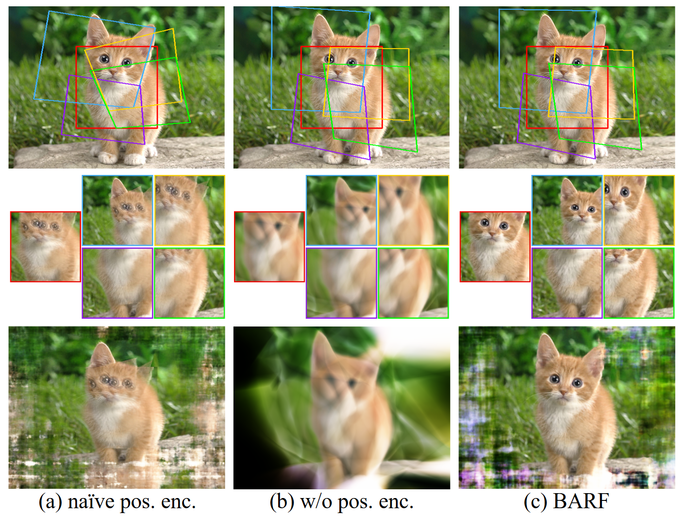
【CameraPoseRefinement】以BARF为例介绍三维重建中的位姿优化
文章目录 IntroductionApproachPlanar Image Alignment(2D)Neural Radiance Fields (3D)Bundle-Adjusting Neural Radiance Fields Experiment平面图像对齐的定性实验合成场景上的定量实验 Introduction 在计算机视觉三维重建中,求解3D场景的表示和定位给定的相机帧…...

YOLO系列论文综述(从YOLOv1到YOLOv11)【第13篇:YOLOv10——实时端到端物体检测】
YOLOv10 1 摘要2 网络结构3 YOLOv1-v10对比 YOLO系列博文: 【第1篇:概述物体检测算法发展史、YOLO应用领域、评价指标和NMS】【第2篇:YOLO系列论文、代码和主要优缺点汇总】【第3篇:YOLOv1——YOLO的开山之作】【第4篇:…...

多数元素
多数元素 给定一个大小为 n 的数组 nums ,返回其中的多数元素。多数元素是指在数组中出现次数 大于 ⌊ n/2 ⌋ 的元素。 你可以假设数组是非空的,并且给定的数组总是存在多数元素。 示例 1: 输入:nums [3,2,3] 输出ÿ…...

EasyDSS视频推拉流技术的应用与安防摄像机视频采集参数
安防摄像机的视频采集参数对于确保监控系统的有效性和图像质量至关重要。这些参数不仅影响视频的清晰度和流畅度,还直接影响存储和网络传输的需求。 安防摄像机图像效果的好坏,由DSP处理器和图像传感器sensor决定,如何利用好已有的硬件资源&…...

在CentOS7上更换为阿里云源
在CentOS 7上更换为阿里云YUM源可以通过以下步骤进行: 备份当前的YUM源配置文件 sudo mv /etc/yum.repos.d/CentOS-Base.repo /etc/yum.repos.d/CentOS-Base.repo.backup 下载阿里云的YUM源配置文件 sudo curl -o /etc/yum.repos.d/CentOS-Base.repo http://mirr…...

小程序跳转到本页面并传参
const pages getCurrentPages(); const currentPage pages[pages.length - 1]; // 当前页面路由 const route currentPage.route; // 当前页面参数 const options currentPage.options;// 构建新的 URL 参数 const newOptions {...options,// newParam: newValue }; // 你…...

Vim操作
1. Vim的模式 2.正常模式->编辑模式 在上⽅插⼊⼀⾏: O在下⽅插⼊⼀⾏: o (open)在当前光标前插⼊: i在⾏⾸插⼊: I在当前光标后插⼊: a在⾏尾插⼊: A 3.常见命令行 1、拷贝当前行 yy ,拷贝当前行向下…...

金碟云星空-企微通知
需求背景: 通过企业微信,及时发送金碟云星空消息,比如流程异常、审批节点、等需要关注数据和信息点 需求目的: 及时告警、高响应、自动化 技能要求: 前后端开发工具的运用与开发,本实例使用IDEA 企业…...

Java中的运算符“instanceof“详解
在Java中,instanceof运算符用于检查一个对象是否是某个特定类的实例,或者是否实现了某个特定接口。它返回一个布尔值(true或false),用于在运行时进行类型检查。这在处理多态性时尤其有用,可以帮助我们确定对…...

传送带突然加速?PLC程序员的翻车现场
基于PLC1200与Factory IO设计的模拟工厂设计 TIA Portal V15.1与Factory IO联机仿真运行系统(不用实物PLC)入下图: 1、有设计程序和仿真环境; 2、有演示视频。前两天在调试Factory IO的立体仓库模型时,传送带突然像脱缰…...

Python测试AI化倒计时:PyPI最新包testgen-ai已突破10万下载量,但93.4%用户仍在用错误配置方式
第一章:Python测试AI化演进与testgen-ai核心定位Python测试生态正经历从手工编写、模板驱动到AI原生生成的关键跃迁。早期依赖unittest和pytest的手动断言构造,逐步被基于代码分析的智能测试生成工具所补充;而当前阶段,大语言模型…...

高效键盘定制指南:Karabiner-Elements 在 macOS 上的专业配置技巧
高效键盘定制指南:Karabiner-Elements 在 macOS 上的专业配置技巧 【免费下载链接】Karabiner-Elements 项目地址: https://gitcode.com/gh_mirrors/kar/Karabiner-Elements Karabiner-Elements 是 macOS 平台上最强大的键盘自定义工具,它允许用…...

告别传统管理低效,拥抱数字化:共建行业新标杆
中国建筑业正处在数字化转型的关键期。行业长期受困于流程繁琐、数据孤岛、协同低效与风险管控滞后等痛点,严重侵蚀利润与效率。面对严格监管与市场竞争,告别传统管理模式,全面拥抱数字化已关乎企业生存。在此背景下,汇聚行业智慧…...

使用CyberChef破解摩斯密码
以CTF编码这道题为例,如下是详细的破解步骤1. 打开 CyberChef访问官方在线地址:https://gchq.github.io/CyberChef/ 界面分为三核心区:- 左侧 Operations:搜索/拖拽操作模块;- 中间 Recipe:堆叠执行的操作流…...

终极指南:使用SnapDOM实现多语言界面的完美对比截图
终极指南:使用SnapDOM实现多语言界面的完美对比截图 【免费下载链接】snapdom snapDOM captures DOM nodes as images with exceptional speed avoiding bottlenecks and long tasks. 项目地址: https://gitcode.com/GitHub_Trending/sn/snapdom SnapDOM是一…...

Cogito-v1-preview-llama-3B部署案例:零基础开发者10分钟跑通本地LLM
Cogito-v1-preview-llama-3B部署案例:零基础开发者10分钟跑通本地LLM 想试试最新的开源大模型,但被复杂的部署步骤劝退?今天,我们就来手把手带你搞定一个性能强劲的本地大语言模型——Cogito-v1-preview-llama-3B。它号称在多项测…...

别再只用RSA了!手把手教你用Java SM2国密算法给接口数据加个密
Java开发者必看:从RSA到SM2国密算法的平滑迁移实战 当我们需要在API接口或数据传输中实现非对称加密时,RSA往往是大多数Java开发者的默认选择。但你可能不知道的是,在相同安全强度下,国密SM2算法的计算速度比RSA快得多,…...

Spring Boot 3 + Vue 3 全栈开发课程指南:从零到独立开发通用管理系统,一篇看懂学什么、怎么学
如果你是一名Java后端开发者,你一定听过这样的声音:“后端程序员也要会前端了。” “毕设要做Web项目,Spring Boot Vue到底怎么学?” “网上课程要么只讲后端接口,要么源码堆砌脱离实际,学完还是不会做项目…...
)
Docker 命令超全详解(入门到运维)
1. 命令简介docker 是一个开源的容器化平台,用于开发、发布和运行应用程序。它允许开发者将应用程序及其所有依赖项(库、运行时、系统工具等)打包到一个标准化的单元中,称为容器。容器是轻量级、可移植、自包含的软件包࿰…...