Halcon 双相机标定与拼图(二)
一、概述
这种标定有两种模式,有一个标定板和多个标定板两种
一个标定板
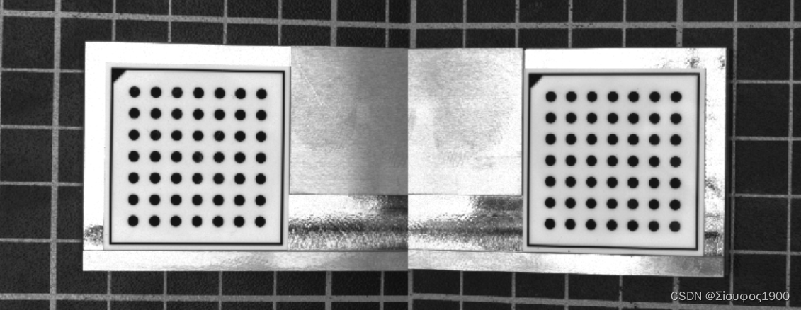
两个相机的重叠区域比较大,那么我们可以把标定板放到那个重叠区域来统一坐标系,如下
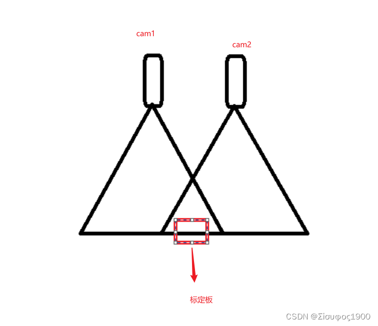
这种是只需要一个标定板,这种是推荐的方式 。这种是比较简单的,今天主要看的第二种
多个标定板
由于要求的视野没有重叠区域,或者重叠的区域太小了,那么我们可以采用这种方式
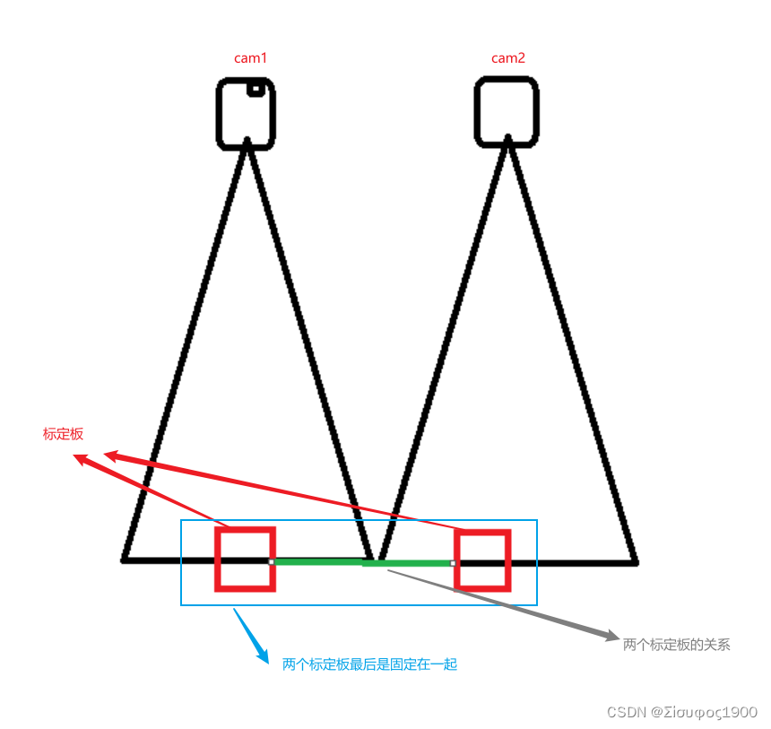
这个方法就是对上面绿色的部分,两个标定板的关系很重要,会直接影响到最后的图像结果
二、算法分析
halcon例程:双相机标定进行高精度对象镶嵌-工业视觉/halcon-少有人走的路
1、相机标定
单独标定连个相机Cam1 Cam2
*两个相机的内参 之前已经标定过了
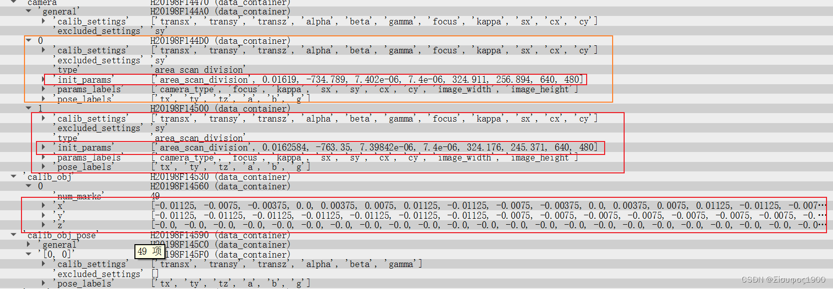
gen_cam_par_area_scan_division (0.01619, -734.789, 7.402e-006, 7.4e-006, 324.911,\256.894, 640, 480, CamParam1)
gen_cam_par_area_scan_division (0.0162584, -763.35, 7.39842e-006, 7.4e-006, 324.176,\245.371, 640, 480, CamParam2)
* 
2、获得姿态Pose
获得各自标定板在各自相机的字体
* 通过相机的内参来而且拍在两个相机中拍同一个标定板
CaltabName := 'caltab_30mm.descr'
*标定参数
*2 表示的是两个相机
* 表示的是只有一个物体object ,这里是指只有一个标定板
create_calib_data ('calibration_object', 2, 1, CalibDataID)*设置标定参数
set_calib_data_calib_object (CalibDataID, 0, CaltabName)set_calib_data_cam_param (CalibDataID, 0, [], CamParam1)
set_calib_data_cam_param (CalibDataID, 1, [], CamParam2)
*
* Find and display the calibration plate in the images.
dev_set_window (WindowHandle1)
find_calib_object (Image1, CalibDataID, 0, 0, 0, [], [])
* 这一步很重要,重要就在计算的那个Pose 表示在相机1 下的姿态* get_calib_data_observ_points( : : CalibDataID, CameraIdx, CalibObjIdx, CalibObjPoseIdx : Row, Column, Index, Pose)功能:从标定数据模型中提取标记点坐标。
* 参数1:CalibDataID:标定数据模型句柄;
* 参数2:CameraIdx:摄像机索引,默认值为0;
* 参数3:CalibObjIdx:标定板索引,默认值0;
* 参数4:CalibObjPoseIdx:观察到的标定板位姿的索引;
* 参数1:( Row, Column):检测到的标记点坐标;
* 参数2: Index:检测到的点与观测到的标定板上的点的对应关系。
* 参数3: Pose:粗略估计观测到的标定板相对于观测相机的姿态。
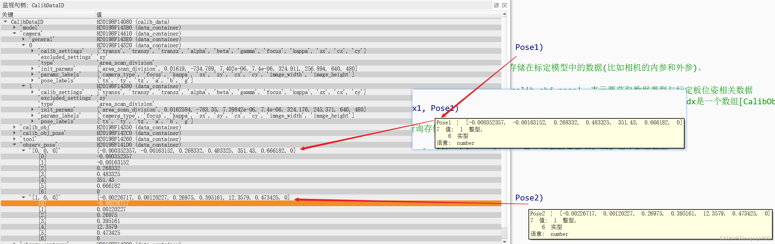
get_calib_data_observ_points (CalibDataID, 0, 0, 0, RowCoord1, ColumnCoord1, Index1, Pose1)* get_calib_data( : : CalibDataID, ItemType, ItemIdx, DataName : DataValue):查询存储在标定模型中的数据(比如相机的内参和外参)。
* 控制输入参数1:CalibDataID:标定数据模型句柄;
* 控制输入参数2:ItemType:数据类型,'camera':表示要获取数据类型是与摄像机相关数据; 'calib_obj_pose':表示要获取数据类型与标定板位姿相关数据
* 控制输入参数3:ItemIdx:ItemIdx:输入参数,ItemType='camera'时,ItemIdx表示摄像机索引;ItemType='calib_obj_pose'时,ItemIdx是一个数组[CalibObjIdx, CalibObjPoseIdx],其中CalibObjIdx表示标定板索引,CalibObjPoseIdx表示参考位姿的图像索引;
* 控制输入参数4:DataName:输入要查询的属性名,'params'表示摄像机内参数; 'pose'表示摄像机外参数;
gen_cross_contour_xld (Cross, RowCoord1, ColumnCoord1, 6, 0.785398)
get_calib_data_observ_contours (Caltab1, CalibDataID, 'caltab', 0, 0, 0)
dev_display (Caltab1)
*
dev_set_window (WindowHandle2)
find_calib_object (Image2, CalibDataID, 1, 0, 0, [], [])
* 这一步很重要,重要就在计算的那个Pose 表示在相机2 下的姿态
get_calib_data_observ_points (CalibDataID, 1, 0, 0, RowCoord2, ColumnCoord2, Index2, Pose2)
gen_cross_contour_xld (Cross2, RowCoord2, ColumnCoord2, 6, 0.785398)
get_calib_data_observ_contours (Caltab2, CalibDataID, 'caltab', 1, 0, 0)
dev_display (Caltab2)此时标定板的情况如下:
3、设置标定板等的厚度
*标定板的厚度 为什么要除以1000
ThicknessCaliper := 2.9 / 1000.0
*平台的厚度
ThicknessPlate := 5.65 / 1000.0
*DiffHeight=先还原到基准面(+ThicknessCaliper)然后再加上要测量的产品的高度(-ThicknessPlate)=ThicknessPlate-ThicknessCaliper
DiffHeight := ThicknessPlate - ThicknessCaliper
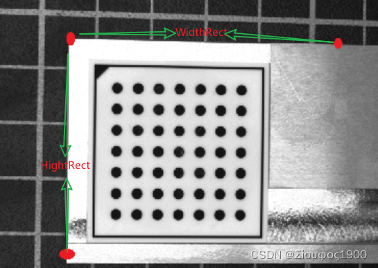
*4、设置裁剪图像以及在不同方向上的差
这个是在宏观意义的,这里只是画一个示意图
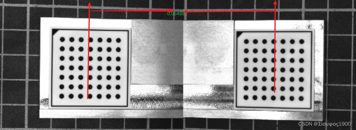
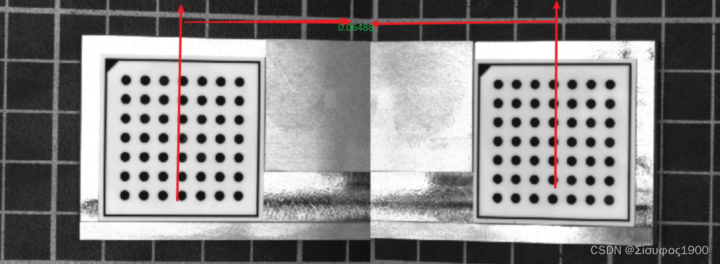
第一个标定和第二个标定板之间的间距如下
*=================================================================================================================================
*DistancePlates 表示连个标定板之间的距离
DistancePlates := 0.06488
*定义马赛克图像的像素大小(以米为单位)。
PixelSize := 0.0001
*
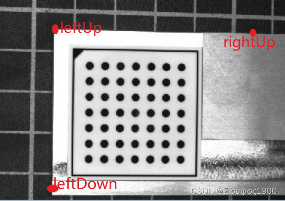
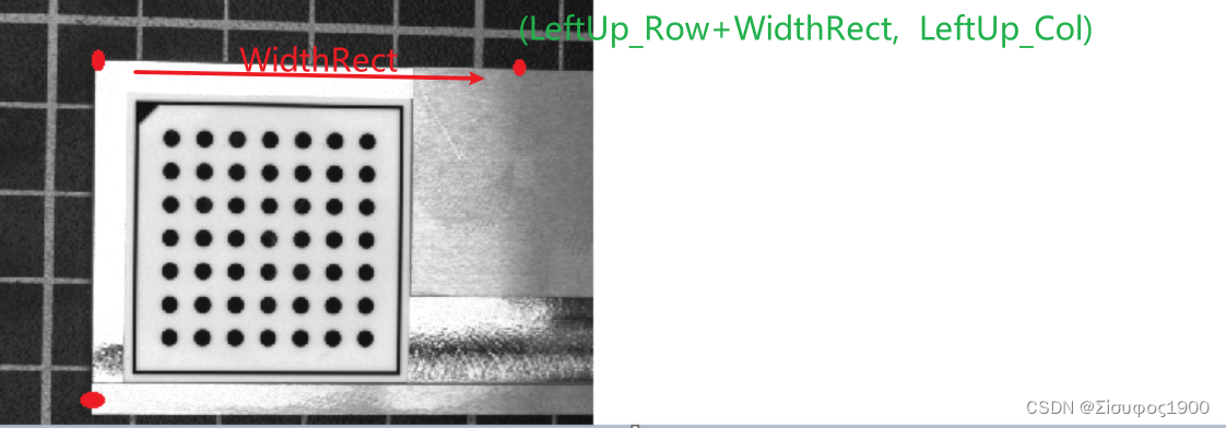
*第一(左)图像,确定必要的转变的姿势很简单。
*您可以根据预先选择的边框宽度在图像坐标中定义校正图像的左上角
BorderInPercent := 3
get_image_size (Image1, WidthImage1, HeightImage1)
* gen_cross_contour_xld (Cross1, HeightImage1, WidthImage1,600, 0.785398)* 图片中左上角的点
UpperRow := HeightImage1 * BorderInPercent / 100.0
LeftColumn := WidthImage1 * BorderInPercent / 100.0
*然后,这个点必须转换成世界坐标。
* image_points_to_world_plane( : : CameraParam, WorldPose, Rows, Cols, Scale : X, Y):将图像点变换到世界坐标系的z=0平面中,* 并返回它们在3D坐标中的X和Y值。* Map1 输出隐射* 控制输入参数1: CameraParam:相机内参;* 控制输入参数2:WorldPose:相机坐标系中世界坐标系的三维姿态(相机外参);* 控制输入参数3: (Rows, Cols):待转换点的坐标;* 控制输入参数4:Scale:比例或尺寸,Default value: 'm';* 控制输出参数:X:世界坐标系中点的X坐标;* 控制输出参数:Y:世界坐标系中点的Y坐标。
image_points_to_world_plane (CamParam1, Pose1, UpperRow, LeftColumn, 'm', Left_Up_X, Left_Up_Y)
* 为了确定校正图像的高度,我们需要定义一个位于第一个图像的下边界附近的点。*左下角的点
LowerRow := HeightImage1 * (100 - BorderInPercent) / 100.0
LeftColumn := WidthImage1 * BorderInPercent / 100.0*同样,这一点必须转换成世界坐标系。
image_points_to_world_plane (CamParam1, Pose1, LowerRow, LeftColumn, 'm', Left_Down_X, Left_Down_Y)
*高度可以确定为左上点和靠近下图像边界的点之间的垂直距离,以校正图像的像素表示。
HeightRect := int((Left_Down_Y - Left_Up_Y) / PixelSize)*类似地,宽度可以由位于两个图像的重叠区域中的一个点来确定,在第一张图片的右边界附近。
OverlapInPercent := 10
RightColumn := WidthImage1 * (100 - OverlapInPercent / 2.0) / 100.0
image_points_to_world_plane (CamParam1, Pose1, UpperRow, RightColumn, 'm', Left_Right_X, Left_Right_Y)
WidthRect := int((Left_Right_X - Left_Up_X) / PixelSize)* 具体示意图如下* X --------------WidthRect-------------- X* |* |* |* |*HeightRect* |* |* |* |* |* X*============================================================================================================================5、计算第二张图像的拼接位置
                              WidthRect, HeightRect, PixelSize, 'bilinear')
*
* Generate a new homogeneous transformation matrix.
*生成一个新的齐次变换矩阵。
hom_mat3d_identity (HomMat3DIdentity)
*
* The second image must be rectified such that it fits exactly
* to the right of the first rectified image. This means that the
* upper left corner of the second rectified image must be identical
* with the upper right corner of the first rectified image.
* Therefore, we need to know the coordinates of the upper right corner
* of the first rectified image in the coordinate system that is defined
* by the calibration plate in the second image.
* First, we express the upper right corner of the first rectified image
* in the world coordinate system that is defined by the calibration plate
* in the first image. It can be determined by a transformation from
* the origin into the upper left corner of the
* first rectified image (a translation) followed by a translation along
* the upper border of the first rectified image. Together with the shift
* that compensates the thickness of the calibration plate, this
* transformation is represented by the homogeneous transformation matrix:
*第二幅图像必须校正,使其正好适合第一幅校正图像的右侧。
*这意味着第二校正图像的左上角必须与第一校正图像的右上角相同。
*因此,我们需要知道第一个校正图像的右上角在由第二个图像中的校准板定义的坐标系中的坐标。
*首先,我们在世界坐标系中表示第一幅校正图像的右上角,该坐标系由第一幅图像中的校准板定义。
*它可以通过从原点到第一校正图像的左上角的变换(平移)以及沿着第一校正图像的上边界的平移来确定。
*与补偿校准板厚度的位移一起,该变换由齐次变换矩阵表示:
second:=Left_Up_X + PixelSize * WidthRect* 第二张图的拼接位置  具体示意图如下
*              first Image                        second Image*  Left_Up_X ----------------------PixelSize * WidthRect---------X----------------------*   |                                          |*   |                                          |*   |                                          |*   |                                          |*   |                                          |*HeightRect                                    |*   |                                          |*   |                                          |*   |                                          |*   |                                          |*   |                                          |*   X                                          |hom_mat3d_translate_local (HomMat3DIdentity, Left_Up_X + PixelSize * WidthRect, Left_Up_Y, DiffHeight, cp1Hur1)
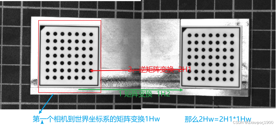
6、第二相机和第一个相机的关系
7、姿态转变矩阵计算
主要是为了得到第二个相机到世界坐标系之间的矩阵变换
DistancePlates是基于第一个相机(0,0,0)到第二个相机的关系
这个就是很简单了,最重要的一步就算完了
get_image_size (Image1, Width1, Height1)
DistancePlates:=0.06488
*DistancePlates:= WidthRect*PixelSize
*DistancePlates 是第一个相机-》第二个相机的矩阵 只是个X方向的移动  1H2
hom_mat3d_translate_local (HomMat3DIdentity, DistancePlates, 0, 0, cp1Hcp2)
*
* Then, we need the transformation between the two calibration plates of
* the calibration object. The homogeneous transformation matrix cp1Hcp2
* describes how the world coordinate system defined by the calibration plate
* in the first image is transformed into the world coordinate system
* defined by the calibration plate in the second image. This transformation
* must be known beforehand from a precise measurement of the calibration object.
* From these two transformations, it is easy to derive
* the transformation that transforms the world coordinate system
* of the second image such that its origin lies in the upper left corner
* of the second rectified image. For this, the two transformations
* have to be combined appropriately.
*然后,我们需要校准对象的两个校准板之间的转换。
*齐次变换矩阵cp1Hcp2描述如何将第一图像中校准板定义的世界坐标系转换为第二图像中校准板定义的世界坐标系。
*这种转换必须事先从校准对象的精确测量中得知。
*从这两个变换,很容易导出变换第二图像的世界坐标系的变换,使得其原点位于第二校正图像的左上角。
*为此,必须将这两个转换适当地结合起来。
*从第二个相机-》第一个相机的比那换
*1H2-》2H1
hom_mat3d_invert (cp1Hcp2, cp2Hcp1)
*相机2-》世界坐标   =2H1*1He  计算从相机二坐标到世界坐标的Pose 转换
hom_mat3d_compose (cp2Hcp1, cp1Hur1, cp2Hul2)
*
* With this, the pose of the calibration plate in the second image
* can be modified such that the origin of the world coordinate system
* lies in the upper left corner of the second rectified image.
*这样,可以修改第二图像中校准板的姿态,使得世界坐标系的原点位于第二校正图像的左上角。
*和上面的同一个道理
pose_to_hom_mat3d (Pose2, cam2Hcp2)
hom_mat3d_compose (cam2Hcp2, cp2Hul2, cam2Hul2)
hom_mat3d_to_pose (cam2Hul2, PoseNewOrigin2)
*
* With the resulting new pose and the size of the rectified image,
* which can be the same as for the first rectified image,
* the rectification map for the second image can be derived.
*根据得到的新姿势和校正图像的大小(其可以与第一校正图像相同),可以导出第二图像的校正地图。
8、生成映射
我们前面算这么多都是为了拿到各个相机的映射,如果是三个相机就是三个映射,四个相机就是4个映射
gen_image_to_world_plane_map (MapSingle2, CamParam2,\PoseNewOrigin2, Width, Height,\WidthRect, HeightRect, PixelSize, 'bilinear')9、贴图
三、代码与效果
*示例程序展示了如何用校准的相机实现高精度的拼接。
*进一步的信息可以在解决方案指南III-C 3D视觉,第9章和第10章中找到。
*本示例程序在第9章中用于说明校准镶嵌。
* 前提,那个标定板放在两个产品的中间,而且两个相机的视野中都能看到完整的标定板
dev_update_off ()
ImgPath := '3d_machine_vision/multiple_cameras/'
*
* Open two windows for the left and the right image.
dev_close_window ()
read_image (Image1, ImgPath + 'camera1_ref')
get_image_size (Image1, Width, Height)
WindowScale := 0.66
dev_open_window (0, 0, Width * WindowScale, Height * WindowScale, 'black', WindowHandle1)
dev_open_window (0, Width * WindowScale + 6, Width * WindowScale, Height * WindowScale,'black', WindowHandle2)
*
* Set some parameters for both windows.
dev_set_window (WindowHandle1)
dev_set_color ('green')
dev_set_draw ('margin')
dev_set_line_width (2)
dev_set_part (0, 0, Height - 1, Width - 1)
set_display_font (WindowHandle1, 16, 'mono', 'true', 'false')
*
dev_set_window (WindowHandle2)
dev_set_color ('green')
dev_set_draw ('margin')
dev_set_line_width (2)
dev_set_part (0, 0, Height - 1, Width - 1)
set_display_font (WindowHandle2, 16, 'mono', 'true', 'false')
*
*两个相机的内参  之前已经标定过了
gen_cam_par_area_scan_division (0.01619, -734.789, 7.402e-006, 7.4e-006, 324.911,\256.894, 640, 480, CamParam1)
gen_cam_par_area_scan_division (0.0162584, -763.35, 7.39842e-006, 7.4e-006, 324.176,\245.371, 640, 480, CamParam2)
*
* Read the images and display them.
read_image (Image1, ImgPath + 'camera1_ref')
read_image (Image2, ImgPath + 'camera2_ref')
dev_set_window (WindowHandle1)
dev_display (Image1)
dev_set_window (WindowHandle2)
dev_display (Image2)
*
* 通过相机的内参来而且拍在两个相机中拍同一个标定板
CaltabName := 'caltab_30mm.descr'
*标定参数
*2 表示的是两个相机
* 表示的是只有一个物体object ,这里是指只有一个标定板
create_calib_data ('calibration_object', 2, 1, CalibDataID)*设置标定参数
set_calib_data_calib_object (CalibDataID, 0, CaltabName)set_calib_data_cam_param (CalibDataID, 0, [], CamParam1)
set_calib_data_cam_param (CalibDataID, 1, [], CamParam2)
*
* Find and display the calibration plate in the images.
dev_set_window (WindowHandle1)
find_calib_object (Image1, CalibDataID, 0, 0, 0, [], [])
* 这一步很重要,重要就在计算的那个Pose 表示在相机1 下的姿态*      get_calib_data_observ_points( : : CalibDataID, CameraIdx, CalibObjIdx, CalibObjPoseIdx : Row, Column, Index, Pose)功能:从标定数据模型中提取标记点坐标。
*      参数1:CalibDataID:标定数据模型句柄;
*      参数2:CameraIdx:摄像机索引,默认值为0;
*      参数3:CalibObjIdx:标定板索引,默认值0;
*      参数4:CalibObjPoseIdx:观察到的标定板位姿的索引;
*      参数1:( Row, Column):检测到的标记点坐标;
*      参数2: Index:检测到的点与观测到的标定板上的点的对应关系。
*      参数3: Pose:粗略估计观测到的标定板相对于观测相机的姿态。
get_calib_data_observ_points (CalibDataID, 0, 0, 0, RowCoord1, ColumnCoord1, Index1, Pose1)*    get_calib_data( : : CalibDataID, ItemType, ItemIdx, DataName : DataValue):查询存储在标定模型中的数据(比如相机的内参和外参)。
*    控制输入参数1:CalibDataID:标定数据模型句柄;
*    控制输入参数2:ItemType:数据类型,'camera':表示要获取数据类型是与摄像机相关数据; 'calib_obj_pose':表示要获取数据类型与标定板位姿相关数据
*    控制输入参数3:ItemIdx:ItemIdx:输入参数,ItemType='camera'时,ItemIdx表示摄像机索引;ItemType='calib_obj_pose'时,ItemIdx是一个数组[CalibObjIdx, CalibObjPoseIdx],其中CalibObjIdx表示标定板索引,CalibObjPoseIdx表示参考位姿的图像索引;
*    控制输入参数4:DataName:输入要查询的属性名,'params'表示摄像机内参数;  'pose'表示摄像机外参数;
gen_cross_contour_xld (Cross, RowCoord1, ColumnCoord1, 6, 0.785398)
get_calib_data_observ_contours (Caltab1, CalibDataID, 'caltab', 0, 0, 0)
dev_display (Caltab1)
*
dev_set_window (WindowHandle2)
find_calib_object (Image2, CalibDataID, 1, 0, 0, [], [])
* 这一步很重要,重要就在计算的那个Pose 表示在相机2 下的姿态
get_calib_data_observ_points (CalibDataID, 1, 0, 0, RowCoord2, ColumnCoord2, Index2, Pose2)
gen_cross_contour_xld (Cross2, RowCoord2, ColumnCoord2, 6, 0.785398)
get_calib_data_observ_contours (Caltab2, CalibDataID, 'caltab', 1, 0, 0)
dev_display (Caltab2)
* * 同一个标定板在不同的相机坐标系下有两个不同的姿态,但是在世界坐标系下两个姿态表示的是同一个东西,同一个姿态。那么这个就是多相机标定的桥梁disp_message (WindowHandle1, 'Calibration successful', 'window', 12, 12, 'black', 'true')
disp_continue_message (WindowHandle1, 'black', 'true')
stop ()
clear_calib_data (CalibDataID)*
* Determine the offset between the calibration plate surface
* and the object surface
* 确定标定板表面与目标表面之间的偏移量*标定板的厚度     为什么要除以1000
ThicknessCaliper := 2.9 / 1000.0
*平台的厚度
ThicknessPlate := 5.65 / 1000.0
*DiffHeight=先还原到基准面(+ThicknessCaliper)然后再加上要测量的产品的高度(-ThicknessPlate)=ThicknessPlate-ThicknessCaliper
DiffHeight := ThicknessPlate - ThicknessCaliper
*
*=================================================================================================================================
*DistancePlates 表示连个标定板之间的距离
DistancePlates := 0.06488
*定义马赛克图像的像素大小(以米为单位)。
PixelSize := 0.0001
*
*第一(左)图像,确定必要的转变的姿势很简单。
*您可以根据预先选择的边框宽度在图像坐标中定义校正图像的左上角
BorderInPercent := 3
get_image_size (Image1, WidthImage1, HeightImage1)
* gen_cross_contour_xld (Cross1, HeightImage1,  WidthImage1,600, 0.785398)* 图片中左上角的点
UpperRow := HeightImage1 * BorderInPercent / 100.0
LeftColumn := WidthImage1 * BorderInPercent / 100.0
*然后,这个点必须转换成世界坐标。
*     image_points_to_world_plane( : : CameraParam, WorldPose, Rows, Cols, Scale : X, Y):将图像点变换到世界坐标系的z=0平面中,*                        并返回它们在3D坐标中的X和Y值。*     Map1 输出隐射*     控制输入参数1: CameraParam:相机内参;*     控制输入参数2:WorldPose:相机坐标系中世界坐标系的三维姿态(相机外参);*     控制输入参数3: (Rows, Cols):待转换点的坐标;*     控制输入参数4:Scale:比例或尺寸,Default value: 'm';*     控制输出参数:X:世界坐标系中点的X坐标;*     控制输出参数:Y:世界坐标系中点的Y坐标。
image_points_to_world_plane (CamParam1, Pose1, UpperRow, LeftColumn, 'm', Left_Up_X, Left_Up_Y)
* 为了确定校正图像的高度,我们需要定义一个位于第一个图像的下边界附近的点。*左下角的点
LowerRow := HeightImage1 * (100 - BorderInPercent) / 100.0
LeftColumn := WidthImage1 * BorderInPercent / 100.0*同样,这一点必须转换成世界坐标系。
image_points_to_world_plane (CamParam1, Pose1, LowerRow, LeftColumn, 'm', Left_Down_X, Left_Down_Y)
*高度可以确定为左上点和靠近下图像边界的点之间的垂直距离,以校正图像的像素表示。
HeightRect := int((Left_Down_Y - Left_Up_Y) / PixelSize)*类似地,宽度可以由位于两个图像的重叠区域中的一个点来确定,在第一张图片的右边界附近。
OverlapInPercent := 10
RightColumn := WidthImage1 * (100 - OverlapInPercent / 2.0) / 100.0
image_points_to_world_plane (CamParam1, Pose1, UpperRow, RightColumn, 'm', Left_Right_X, Left_Right_Y)
WidthRect := int((Left_Right_X - Left_Up_X) / PixelSize)* 具体示意图如下*    X --------------WidthRect-------------- X*   |*   |*   |*   |*HeightRect*   |*   |*   |*   |*   |*  X*============================================================================================================================
*利用变换后的姿态和校正后图像的大小,可以得到第一幅图像的校正图。
set_origin_pose (Pose1, Left_Up_X, Left_Up_Y, DiffHeight, PoseNewOrigin1)*
gen_image_to_world_plane_map (MapSingle1, CamParam1, PoseNewOrigin1, Width, Height, \WidthRect, HeightRect, PixelSize, 'bilinear')
*
* Generate a new homogeneous transformation matrix.
*生成一个新的齐次变换矩阵。
hom_mat3d_identity (HomMat3DIdentity)
*
* The second image must be rectified such that it fits exactly
* to the right of the first rectified image. This means that the
* upper left corner of the second rectified image must be identical
* with the upper right corner of the first rectified image.
* Therefore, we need to know the coordinates of the upper right corner
* of the first rectified image in the coordinate system that is defined
* by the calibration plate in the second image.
* First, we express the upper right corner of the first rectified image
* in the world coordinate system that is defined by the calibration plate
* in the first image. It can be determined by a transformation from
* the origin into the upper left corner of the
* first rectified image (a translation) followed by a translation along
* the upper border of the first rectified image. Together with the shift
* that compensates the thickness of the calibration plate, this
* transformation is represented by the homogeneous transformation matrix:
*第二幅图像必须校正,使其正好适合第一幅校正图像的右侧。
*这意味着第二校正图像的左上角必须与第一校正图像的右上角相同。
*因此,我们需要知道第一个校正图像的右上角在由第二个图像中的校准板定义的坐标系中的坐标。
*首先,我们在世界坐标系中表示第一幅校正图像的右上角,该坐标系由第一幅图像中的校准板定义。
*它可以通过从原点到第一校正图像的左上角的变换(平移)以及沿着第一校正图像的上边界的平移来确定。
*与补偿校准板厚度的位移一起,该变换由齐次变换矩阵表示:
second:=Left_Up_X + PixelSize * WidthRect* 第二张图的拼接位置  具体示意图如下
*              first Image                        second Image*  Left_Up_X ----------------------PixelSize * WidthRect---------X----------------------*   |                                          |*   |                                          |*   |                                          |*   |                                          |*   |                                          |*HeightRect                                    |*   |                                          |*   |                                          |*   |                                          |*   |                                          |*   |                                          |*   X                                          |hom_mat3d_translate_local (HomMat3DIdentity, Left_Up_X + PixelSize * WidthRect, Left_Up_Y, DiffHeight, cp1Hur1)get_image_size (Image1, Width1, Height1)
DistancePlates:=0.06488
*DistancePlates:= WidthRect*PixelSize
*DistancePlates 是第一个相机-》第二个相机的矩阵 只是个X方向的移动  1H2
hom_mat3d_translate_local (HomMat3DIdentity, DistancePlates, 0, 0, cp1Hcp2)
*
* Then, we need the transformation between the two calibration plates of
* the calibration object. The homogeneous transformation matrix cp1Hcp2
* describes how the world coordinate system defined by the calibration plate
* in the first image is transformed into the world coordinate system
* defined by the calibration plate in the second image. This transformation
* must be known beforehand from a precise measurement of the calibration object.
* From these two transformations, it is easy to derive
* the transformation that transforms the world coordinate system
* of the second image such that its origin lies in the upper left corner
* of the second rectified image. For this, the two transformations
* have to be combined appropriately.
*然后,我们需要校准对象的两个校准板之间的转换。
*齐次变换矩阵cp1Hcp2描述如何将第一图像中校准板定义的世界坐标系转换为第二图像中校准板定义的世界坐标系。
*这种转换必须事先从校准对象的精确测量中得知。
*从这两个变换,很容易导出变换第二图像的世界坐标系的变换,使得其原点位于第二校正图像的左上角。
*为此,必须将这两个转换适当地结合起来。
*从第二个相机-》第一个相机的比那换
*1H2-》2H1
hom_mat3d_invert (cp1Hcp2, cp2Hcp1)
*相机2-》世界坐标   =2H1*1He  计算从相机二坐标到世界坐标的Pose 转换
hom_mat3d_compose (cp2Hcp1, cp1Hur1, cp2Hul2)
*
* With this, the pose of the calibration plate in the second image
* can be modified such that the origin of the world coordinate system
* lies in the upper left corner of the second rectified image.
*这样,可以修改第二图像中校准板的姿态,使得世界坐标系的原点位于第二校正图像的左上角。
*和上面的同一个道理
pose_to_hom_mat3d (Pose2, cam2Hcp2)
hom_mat3d_compose (cam2Hcp2, cp2Hul2, cam2Hul2)
hom_mat3d_to_pose (cam2Hul2, PoseNewOrigin2)
*
* With the resulting new pose and the size of the rectified image,
* which can be the same as for the first rectified image,
* the rectification map for the second image can be derived.
*根据得到的新姿势和校正图像的大小(其可以与第一校正图像相同),可以导出第二图像的校正地图。
gen_image_to_world_plane_map (MapSingle2, CamParam2,\PoseNewOrigin2, Width, Height,\WidthRect, HeightRect, PixelSize, 'bilinear')
*
* Open a new Graphics Window for the merged image.
*打开合并图像的新图形窗口。
dev_open_window (Height * WindowScale, 0, Width * 2 * WindowScale, Height * WindowScale, \'black', WindowHandleCombined)
set_display_font (WindowHandleCombined, 16, 'mono', 'true', 'false')
dev_set_color ('green')
dev_set_draw ('margin')
ScalePlot := 200
RowPlot := 400
Coord := [0:2000]
*
*  Process all image pairs in a loop.
*循环处理所有图像对
for I := 1 to 3 by 1* * Display both images.dev_set_window (WindowHandle1)read_image (Image1, ImgPath + 'camera1_' + I$'02d')get_image_size (Image1, WidthImage1, HeightImage1)dev_set_part (0, 0, HeightImage1 - 1, WidthImage1 - 1)dev_display (Image1)dev_set_window (WindowHandle2)read_image (Image2, ImgPath + 'camera2_' + I$'02d')get_image_size (Image2, WidthImage2, HeightImage2)dev_set_part (0, 0, HeightImage2 - 1, WidthImage2 - 1)dev_display (Image2)*     tile_images(Image1, Image2, 2, 'vertical')* * Start the time measurement.count_seconds (TimeStart1)* * Rectify the image pair from the two-camera setup with map_image.*使用map_image校正两个摄像机设置中的图像对map_image (Image1, MapSingle1, RectifiedImage1)
*    get_image_size (RectifiedImage1, Width2, Height2)map_image (Image2, MapSingle2, RectifiedImage2)
*    get_image_size (RectifiedImage2, Width44, Height44)concat_obj (RectifiedImage1, RectifiedImage2, Concat)* End the time measurement and calculate the difference.*结束时间测量并计算差异count_seconds (TimeEnd1)Time1 := TimeEnd1 - TimeStart1* dev_set_window (WindowHandleCombined)* Start the time measurement again.count_seconds (TimeStart2)* * Tile both images into one large image.* 将两个图像平铺成一个大图像tile_images (Concat, Combined, 2, 'vertical')get_image_size (Combined, Width3, Height3)* * End the time measurement again and calculate the difference.count_seconds (TimeEnd2)Time2 := TimeEnd2 - TimeStart2* * Display the combined image and the time measurement.get_image_size (Combined, WidthComb, HeightComb)dev_set_part (0, 0, HeightComb - 1, WidthComb - 1)dev_display (Combined)disp_message (WindowHandle1, 'Merge cameras: ' + (1000 * (Time1 + Time2))$'.3' + ' ms', \'window', 12, 12, 'black', 'true')* * In addition, we plot the accuracy of the mosaicking with a procedure.*此外,我们用一个程序来绘制马赛克的准确性。plot_mosaicking_accuracy (Combined, WidthRect, HeightRect, WindowHandleCombined, Coord, ScalePlot, RowPlot)if (I < 3)disp_continue_message (WindowHandleCombined, 'black', 'true')stop ()endif
endfor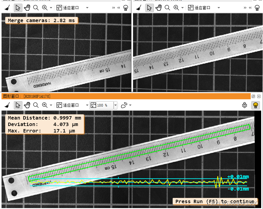
四、疑问
虽然上面的原理我懂了,但是对于这种方法有几个细节东西还有疑惑,望各位帮忙
1、加入两个标定板直接不仅有平移关系,还有旋转关系,只是在两个标定板之间再添加一个旋转关系吗,对于高精度的项目来说,两个标定板的厚度是不是要做一个矫正?
2、在实际的项目中,标定板如何定做,对精度有要求的,不然可以直接打印一张纸上画两个标定板
3、我们在标定的时候已经有内参了,但是在生成映射gen_image_to_world_plane_map的时候为什么采用的像素当量不一样,内参中也有每个像素的大小啊??
4、gen_image_to_world_plane_map中算子中scale 的理解,其实就是第三个问题
我们都是站在历史巨人的肩膀上实践的,希望各位能帮忙一下
参考博文:双相机融合标定_双相机标定拼图-CSDN博客
相关文章:
Halcon 双相机标定与拼图(二)
一、概述 这种标定有两种模式,有一个标定板和多个标定板两种 一个标定板 两个相机的重叠区域比较大,那么我们可以把标定板放到那个重叠区域来统一坐标系,如下 这种是只需要一个标定板,这种是推荐的方式 。这种是比较简单的&…...

【加密与解密】【04】Java安全架构
JAVA安全模块划分 JCA,Java Cryptography Architecture,Java加密体系结构JCE,Java Cryptography Extension,Java加密扩展包JSSE,Java Secure Sockets Extension,Java安全套接字扩展包JAAS,Java…...

论文阅读:Neural Scene Flow Prior
目录 概要 Motivation 整体架构流程 技术细节 小结 论文地址:...

如何通过 6 种简单方法将照片从华为转移到 PC?
华为作为全球领先的智能手机供应商之一,最近推出了其自主研发的操作系统——HarmonyOS 2.0,旨在为智能手机、平板电脑和智能手表等设备提供更流畅的用户体验。随着Mate 40/P40等系列手机计划升级到HarmonyOS 2.0,用户可能需要将手机中的文件备…...
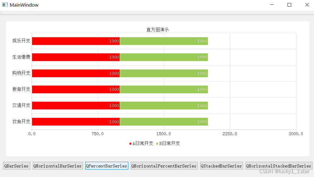
QtCharts使用
1.基础配置 1.QGraphicsView提升为QChartView#include <QtCharts> QT_CHARTS_USE_NAMESPACE #include "ui_widget.h"2. QT charts 2.柱状图 2.1QBarSeries //1.创建Qchart对象QChart *chart new QChart();chart->setTitle("直方图演示");//设…...

深入分析 Flink SQL 工作机制
摘要:本文整理自 Flink Forward 2020 全球在线会议中文精华版,由 Apache Flink PMC 伍翀(云邪)分享,社区志愿者陈婧敏(清樾)整理。旨在帮助大家更好地理解 Flink SQL 引擎的工作原理。文章主要分…...

Spring Bean参数校验Validator
Spring Bean参数校验Validator 以下2种方式可以用于所有的 Spring bean 不仅仅是 Controller 控制器。 一、原始类型参数 在控制器(或者其他Bean)上使用Validated注解。 控制器类 RestController RequestMapping("account") Validated pub…...
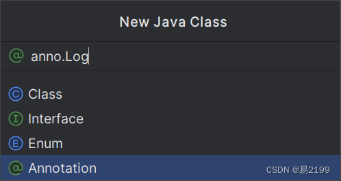
AOP案例
黑马程序员JavaWeb开发教程 文章目录 一、案例1.1 案例1.2 步骤1.2.1 准备1.2.2 编码 一、案例 1.1 案例 将之前案例中增、删、改相关节后的操作日志记录到数据库表中。 操作日志:日志信息包含:操作人、操作时间、执行方法的全类名、执行方法名、方法…...

Facebook海外户Facebook广告被暂停的原因
有很多伙伴在Facebook广告时,有时会遇到账号被暂停,并通知你违反了哪些规则,那么Facebook广告被暂停的原因有哪些呢?今天小编详细梳理了一些原因,可以往下看哦~ 您的Facebook广告被暂停可能有以下几个原因:…...

网站企业需要适用于什么服务器?
对于网站企业会选择什么样的服务器呢? 为了保证网站能够稳定的运行需要选择高可用性和可靠性的网站服务器,选择具备高可用性架构的云服务器供应商,能够提供多可用区部署、自动故障转移和备份恢复等功能,保障网站在各种故障情况下的…...
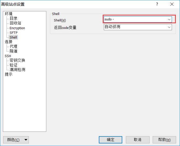
winscp无法上传,删除,修改文件并提示权限不够的分析
使用winscp删除文件,报了个错如下 根据这个错就去百度,网上大部分都是通过下面这种方法解决: 在winscp端进行设置 输入主机名(即IP地址)、用户名和密码,然后点击高级 在箭头所指位置输入sudo + sftp应用程序的路径 先查询 sudo find / -name sftp-server -print点击Sh…...

Hadoop3:MapReduce之InputFormat数据输入过程整体概览(0)
一、MapReduce中数据流向 二、MapTask并行度 1、原理概览 数据块:Block是HDFS物理上把数据分成一块一块。数据块是HDFS存储数据单位。 数据切片:数据切片只是在逻辑上对输入进行分片,并不会在磁盘上将其切分成片进行存储。数据切片是MapRed…...

【Leetcode Python】70.爬楼梯
麻烦大家要自己去leetcode看题目 第一个思路 用递归会超时 return self.climbStairs(n - 1) self.climbStairs(n - 2)第二个思路 滚动数组思想 class Solution(object):def climbStairs(self, n):""":type n: int:rtype: int"""if(n<2)…...

深度学习 - 张量的广播机制和复杂运算
张量的广播机制(Broadcasting)是一种处理不同形状张量进行数学运算的方式。通过广播机制,PyTorch可以自动扩展较小的张量,使其与较大的张量形状兼容,从而进行元素级的运算。广播机制遵循以下规则: 如果张量…...

【CSS】will-change 属性详解
目录 基本语法属性值常见用途will-change 如何用于优化动画效果示例: will-change 是一个 CSS 属性,用于告诉浏览器某个元素在未来可能会发生哪些变化。这可以帮助浏览器优化渲染性能,提前做一些准备工作,从而提高性能。 基本语法…...
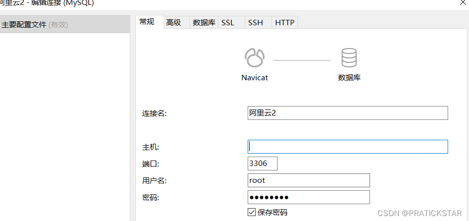
linux安装mysql后,配置mysql,并连接navicat软件
Xshell连接登陆服务器 输入全局命令 mysql -u root -p 回车后,输入密码,不显示输入的密码 注意mysql服务状态,是否运行等 修改配置文件my.cnf,这里没找到就找my.ini,指定有一个是对的 find / -name my.cnf 接下…...

【学习笔记】Axios、Promise
TypeScript 1、Axios 1.1、概述 1.2、axios 的基本使用 1.3、axios 的请求方式及对应的 API 1.4、axios 请求的响应结果结构 1.5、axios 常用配置选项 1.6、axios.create() 1.7、拦截器 1.8、取消请求2、Promise 2.1、封装 fs 读…...
)
自然资源-关于加强规划实施监督管理的指导意见(浙江省自然资源厅学习借鉴)
自然资源-关于加强规划实施监督管理的指导意见(浙江省自然资源厅(征求意见稿)学习借鉴 以下为征求意见稿的内容,很多干活: 各市、县(市、区)自然资源主管部门: 为加强国土空间规划…...

408链表的创建和初始化
首先第一个头文件,定义结构体类型 typedef struct LNode {int data;struct LNode* next; }LNode,*LinkList; //可能作为第一次写c语言的小伙伴看不懂这一段typedef是如何定义的 //基本的解释如下所示 //typedef struct LNode LNode; //typedef struct LNode* LinkL…...

Python数据框/列表生成一列多个同样的值
例1:Python生成100个数字2 方法一: import numpy as np a np.random.randint(2,3,100) 方法二: a [2] list a * 100 #100个数字2的列表 例2:生成100个字符串棒 b 棒 list_b b * 100...

FDL能解决哪些数据集成痛点?新手如何快速上手FDL
最近后台不少刚接触数据集成的小伙伴问我,刚开始做数据同步、接口对接这些工作,有没有什么能快速上手的工具和方法。这让我想起自己刚转行做数据运维的时候,面对一堆乱糟糟的业务数据,完全不知道从哪下手。今天我就结合自己这几年…...

**Prompt工程与模板化管理**是让AI从“能用“到“好用“的关键。
结合你之前对AI代码生成器和LangChain4j的探索,Prompt工程与模板化管理是让AI从"能用"到"好用"的关键。让我全面解析这两个紧密相关的概念: 一、什么是Prompt工程? Prompt工程(提示词工程)是设计和优化输入提示词,以引导AI模型生成期望输出的技术。…...

基于LangChain的RAG与Agent智能体开发 - OpenAI库介绍和使用
大家好,我是小锋老师,最近更新《2027版 基于LangChain的RAG与Agent智能体 开发视频教程》专辑,感谢大家支持。本课程主要介绍和讲解RAG,LangChain简介,接入通义千万大模型,Ollama简介以及安装和使用&#x…...

AI 模型推理系统的延迟优化方案
AI模型推理系统的延迟优化方案 随着AI技术的广泛应用,模型推理延迟成为影响用户体验和系统性能的关键因素。无论是实时语音识别、自动驾驶,还是在线推荐系统,高延迟都会降低响应速度,甚至导致业务损失。如何优化AI推理系统的延迟…...

ubuntu vnc 问题汇总
第一部分:使用虚拟显示管理器 如何让树莓派不连接显示器,也能在windows上用vnc访问? 如题配置完成后,树莓派就可以在不连接物理显示器的情况下通过VNC远程访问了。 1. 安装必要的包 sudo apt install xserver-xorg-video-dumm…...
)
从入门到精通:AgentCPM-GUI用户操作完全手册(含实战案例)
从入门到精通:AgentCPM-GUI用户操作完全手册(含实战案例) 【免费下载链接】AgentCPM-GUI AgentCPM-GUI: An on-device GUI agent for operating Android apps, enhancing reasoning ability with reinforcement fine-tuning for efficient ta…...

霜儿-汉服-造相Z-Turbo实战教程:使用ComfyUI替代Gradio实现节点化汉服生成流程
霜儿-汉服-造相Z-Turbo实战教程:使用ComfyUI替代Gradio实现节点化汉服生成流程 1. 教程概述与学习目标 本教程将带你学习如何使用ComfyUI替代Gradio,为霜儿-汉服-造相Z-Turbo模型构建一个节点化的汉服图片生成流程。通过本教程,你将掌握&am…...

一次线上事故,我学到了事件驱动架构的5个教训
凌晨3点17分,监控大屏突然一片血红。用户订单"成功"了,但库存没扣、支付没扣、物流没发...上百万的交易数据人间蒸发。排查结果让所有人傻眼:只是一个"无关紧要"的代码改动,让整个事件驱动系统安静地"死…...
✅)
计算机毕业设计源码:Python贝壳租房数据可视化与智能推荐系统 Scrapy爬虫 可视化 推荐系统 大数据 数据分析 大模型 房源 房子(建议收藏)✅
博主介绍:✌全网粉丝10W,前互联网大厂软件研发、集结硕博英豪成立工作室。专注于计算机相关专业项目实战6年之久,选择我们就是选择放心、选择安心毕业✌ > 🍅想要获取完整文章或者源码,或者代做,拉到文章底部即可与…...

赋能中国企业出海:欧洲展台搭建欧标实操解析与孚锐实践
随着中国企业全球化布局持续深化,欧洲作为全球会展业的核心阵地,凭借成熟的行业体系、广阔的市场潜力,成为中国企业出海展示品牌实力的重要舞台。展台作为品牌与欧洲市场对话的核心载体,其搭建质量不仅关乎品牌形象,更…...